24
ASSEMBLY
The assembly of the Rammer is the reverse of the disassembly procedure with the addition of the following steps.
Prior to assembly, wash all parts in a suitable cleaner or solvent. Check moving parts for wear and failure. Refer
to the
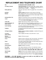
REPLACEMENT CHART
for tolerances and replacement cycles. For torque settings other than those listed
see
TORQUE CHART
.
GEARBOX ASSEMBLY:
1. Ensure that Bearings press on square and seat
properly.
2. Be sure Retaining Ring (Fig 7, #9) is on the Crank
Gear (Fig 7, #6) before the Bearing (Fig 7, #7) is
pressed on.
3. While pressing the Pinion into the Gearbox,
do not
use excessive pressure to seat the Pinion.
4. Lightly oil the OĆRing (Fig 7 #15) before installing
it into the Cover (Fig 7, #1).
5. Apply Loctite #242 to six Flange Whiz Lock Screws
(Fig 7, #16) and install. Tighten equally and torque
to 12 ft lbs (16 N
m).
6. If the Shockmounts (Fig 7, #22) were removed,
apply Loctite #242 to the four Socket Head Cap
Screws (Fig 7, #23) before assembly. Torque the
four Socket Head Cap Screws to 35 ft lbs (47 N
m).
7. Replace Seal Washer (Fig 7, #17) if damaged.
Do
not
over tighten Hex Head Cap Screw (Fig 7, #18).
8. Use Loctite #242 on the Breather Tube Assembly
(Fig 7, #30). Torque to 50 ft lbs (68 N
m).
9. Before installing the Gearbox to the Lower System,
install a new Gasket (Fig 7, #26) on the top of the
Lower System.
10. Torque the four Socket Head Cap Screws (Fig 7,
#29) holding the Gearbox to the Lower System to
60 ft lbs (81 N
m).
LOWER SYSTEM ASSEMBLY
:
1. The Elastic Stop Nut (Fig 9, #18) must be replaced
and torqued to 100 ft lbs (135 N
m).
2. Lightly grease the OĆRing groove in the Cover (Fig
9, #20) before installing the OĆRing (Fig 9, #19).
Use the two Spring Box Tools to draw the Cover
down onto the Spring Box.
3. Install three Flat Head Socket Screws (Fig 9, #21)
and torque to 8 ft lbs (11 N
m).
The spring box WARNING DECAL (Fig 9, #24)
should be clean and highly visible. If it is not, the
old decal should be completely removed and
replaced.
4. Before sliding Mount (Fig 9, #7) on to Spring Box,
lightly oil OĆRing (Fig 9, #8) and place it into the
groove in the Mount.
5. Torque the six (6) Hex Nuts (Fig 9, #27) holding the
Shoe to the Spring Box to 50 ft lbs (67 N
m).
HANDLE (AIRAMMER):
1. Slide Valve Block (Fig 16, #18) back and forth on
Handle (Fig 16, #1) as required before tightening
Clamps (Fig 16, #4) to ensure that the Actuator
Arm (Fig 16, #5) does not bind.
2. Adjust Set Screw (Fig 6, #17) as required to ensure
that: (see Figure 6)
a. When Actuator Arm (Fig 6, #5) is released,
valve is completely closed.
b. When Actuator Arm (Fig 6, #5) is raised, valve
is fully opened and no air is exhausted from the
lower vent hole.
FIGURE 6
.00"-.10"
5
17
NOMINAL ADJUSTMENT
Содержание R270R
Страница 29: ...27 FIGURE 7 270 450 451 GEARBOX ...
Страница 31: ...29 FIGURE 8 374 376 GEARBOX ...
Страница 33: ...31 FIGURE 9 270 450 451 LOWER SYSTEM ...
Страница 35: ...33 FIGURE 10 374 376 LOWER SYSTEM ...
Страница 37: ...35 FIGURE 11 270 450 451 HANDLE ...
Страница 39: ...37 FIGURE 12 STANDARD HANDLE OIL INJECTED ONLY ...
Страница 41: ...39 FIGURE 13 374 376 HANDLE ...
Страница 43: ...41 FIGURE 14 LO PROFILE HANDLE 1 3 6 10 11 13 11 9 ...
Страница 45: ...43 FIGURE 15 LO PROFILE HANDLE OIL INJECTED ONLY ...
Страница 49: ...47 FIGURE 17 ROBIN ENGINE ...
Страница 51: ...49 FIGURE 18 ROBIN OIL INJECTED ENGINE ...
Страница 53: ...51 FIGURE 19 LO PROFILE ROBIN ENGINE ...
Страница 55: ...53 FIGURE 20 AIRAMMER MOTOR 2 6 5 4 3 1 9 8 7 TO VALVE BLOCK TO MOTOR INLET ...


