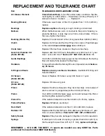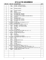
20
DISASSEMBLY
GENERAL
The disassembly and assembly procedures given on the next few pages are intended for a complete dismantling
of the various Rammer models. Read the following sections carefully and refer to the appropriate sections for the
rammer being repaired. It is not necessary to follow the complete disassembly procedure when only partial
disassembly is required. If repairs have to be made to the Lower System only, it is recommended that the Drive Unit
(Engine, Gearbox and Handle) be removed from the Lower System. See Lower System" disassembly.
HANDLE REMOVAL:
GASOLINE RAMMERS:
1. Turn off the Fuel Valve (Fig 11, #8).
2. Loosen Hose Clamp (Fig 11, #22) and disconnect
the Fuel Line from the Carburetor.
3. Remove the hardware holding the Throttle (Fig 11,
#15,#16 & #19) to the Handle.
4. Remove four (4) Flange Whiz Lock Screws (Fig 11,
#2) and lift the Handle free from the Rammer.
PNEUMATIC RAMMERS:
1. Disconnect the compressed air supply hose at the
rammer handle valve block.
Ensure that air supply hoses have been
depressurized before disconnecting.
2. Disconnect the air hose at the pneumatic motor.
3. Remove four (4) Socket Head Cap Screws (Fig 7,
#23) and lift the Handle free from the Rammer.
MOTOR REMOVAL:
It is not necessary to remove the Handle to take the Engine off the machine.
GASOLINE ENGINE :
1. Remove the two (2) Flange WhizĆLock Screws (Fig
17, #10). Remove the four (4) Hex Head Cap
Screws and Lockwashers (Fig 17, #4 & #3)
holding the Engine (Fig 17, #1) and Spacer (Fig
17, #2) to the Gearbox.
2. The Engine and Spacer can now be removed from
the machine.
PNEUMATIC MOTOR (TCS):
1. Remove the four (4) Hex Head Cap Screws and
Lockwashers (Fig 20, #6 & #5) holding the Motor
(Fig 20, #7) to the Gearbox.
2. The Motor can now be removed from the machine.
CENTRIFUGAL CLUTCH:
1. The Clutch (Fig 17, #7) can be removed from the
Engine by using the
MBW Clutch Removal Tool
#07353
.
2. Reinstall the Clutch to the Engine P.T.O. Shaft finger
tight.
Содержание R270R
Страница 29: ...27 FIGURE 7 270 450 451 GEARBOX ...
Страница 31: ...29 FIGURE 8 374 376 GEARBOX ...
Страница 33: ...31 FIGURE 9 270 450 451 LOWER SYSTEM ...
Страница 35: ...33 FIGURE 10 374 376 LOWER SYSTEM ...
Страница 37: ...35 FIGURE 11 270 450 451 HANDLE ...
Страница 39: ...37 FIGURE 12 STANDARD HANDLE OIL INJECTED ONLY ...
Страница 41: ...39 FIGURE 13 374 376 HANDLE ...
Страница 43: ...41 FIGURE 14 LO PROFILE HANDLE 1 3 6 10 11 13 11 9 ...
Страница 45: ...43 FIGURE 15 LO PROFILE HANDLE OIL INJECTED ONLY ...
Страница 49: ...47 FIGURE 17 ROBIN ENGINE ...
Страница 51: ...49 FIGURE 18 ROBIN OIL INJECTED ENGINE ...
Страница 53: ...51 FIGURE 19 LO PROFILE ROBIN ENGINE ...
Страница 55: ...53 FIGURE 20 AIRAMMER MOTOR 2 6 5 4 3 1 9 8 7 TO VALVE BLOCK TO MOTOR INLET ...

