21
GEARBOX REMOVAL:
Remove the handle and the motor as previously instructed.
R270, R450, R451:
1. Remove the Socket Head Cap Screws and
Lockwashers (Fig 7, #29 & #28) holding the
Gearbox to the Lower System.
2. Push the Guide Tube (Fig 9, #3) down until it
exposes the Ram Head and Piston Pin (Fig 7, #27).
While holding the Gearbox, tap out the Piston Pin
with a hammer and drift pin. The Gearbox may
now be removed from the Lower System. See
Figure 1.
FIGURE 1
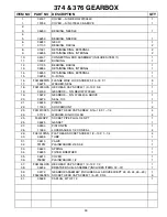
R374, R376:
1. Remove the Socket Head Cap Screws (Fig 8, #40)
from the top of the Guide Tube flange.
2. Push the Bellows and Rubber Gasket down until
the Flat Head Socket Screws are exposed (Fig 8,
#29). Remove the flat head socket screws and
Conical Lockwashers (Fig 8, #29 & #28). The
conical washers may not be reused. New conical
washers must be used upon assembly.
3. Push the Guide Tube (Fig 10, #3) down until it
exposes the Ram Head and Piston Pin (Fig 7, #27).
While holding the Gearbox, tap out the Piston Pin
with a hammer and drift pin. The Gearbox may
now be removed from the Lower System. See
Figure 2.
FIGURE 2
Содержание R270R
Страница 29: ...27 FIGURE 7 270 450 451 GEARBOX ...
Страница 31: ...29 FIGURE 8 374 376 GEARBOX ...
Страница 33: ...31 FIGURE 9 270 450 451 LOWER SYSTEM ...
Страница 35: ...33 FIGURE 10 374 376 LOWER SYSTEM ...
Страница 37: ...35 FIGURE 11 270 450 451 HANDLE ...
Страница 39: ...37 FIGURE 12 STANDARD HANDLE OIL INJECTED ONLY ...
Страница 41: ...39 FIGURE 13 374 376 HANDLE ...
Страница 43: ...41 FIGURE 14 LO PROFILE HANDLE 1 3 6 10 11 13 11 9 ...
Страница 45: ...43 FIGURE 15 LO PROFILE HANDLE OIL INJECTED ONLY ...
Страница 49: ...47 FIGURE 17 ROBIN ENGINE ...
Страница 51: ...49 FIGURE 18 ROBIN OIL INJECTED ENGINE ...
Страница 53: ...51 FIGURE 19 LO PROFILE ROBIN ENGINE ...
Страница 55: ...53 FIGURE 20 AIRAMMER MOTOR 2 6 5 4 3 1 9 8 7 TO VALVE BLOCK TO MOTOR INLET ...


