background image

Operator's

Safety

and

Service

Manual

RAMMERS

L12219 / 06.01

MBW Inc 2001

Printed in U.S.A.

MBW INC.

250 HARTFORD ROAD 


P.O. BOX 440

SLINGER, WI  53086-0440

PHONE: (262) 644-5234 


FAX (262) 644-5169

MBW CORPORATE INTERNET ADDRESS

E-MAIL: [email protected]

WEB SITE: www.mbw.com

IN ENGLAND:

MBW (UK) LIMITED

Bradley Fold Trading Estate Unit 6

Radcliffe Moor Road

Bolton BL2 6RT

Phone: 01204 387784 


FAX: 01204 387797

It is the OWNER'S RESPONSIBILITY to communicate information on the

SAFE USE and OPERATION of this machine to the operators!

Содержание R270R

Страница 1: ...262 644 5234 FAX 262 644 5169 MBW CORPORATE INTERNET ADDRESS E MAIL mbw mbw com WEB SITE www mbw com IN ENGLAND MBW UK LIMITED Bradley Fold Trading Estate Unit 6 Radcliffe Moor Road Bolton BL2 6RT Phone 01204 387784 FAX 01204 387797 It is the OWNER S RESPONSIBILITY to communicate information on the SAFE USE and OPERATION of this machine to the operators ...

Страница 2: ...NTENANCE 18 DISASSEMBLY 20 ASSEMBLY 24 KITS TORQUE CHART 25 REPLACEMENT AND TOLERANCE CHART 26 270 450 451 GEARBOX 27 374 376 GEARBOX 29 270 450 451 LOWER SYSTEM 31 374 376 LOWER SYSTEM 33 270 450 451 HANDLE 35 STANDARD HANDLE OIL INJECTED RAMMERS 37 374 376 HANDLE 39 LO PROFILE HANDLE 41 LO PROFILE HANDLE OIL INJECTED RAMMERS 43 AIRAMMER HANDLE 45 ROBIN ENGINE ASSEMBLY 47 ROBIN OIL INJECTED ENGIN...

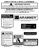
Страница 3: ...NOISE PROTECTION Wear O S H A specified hearing protection devices FOOT PROTECTION Wear O S H A specified steel tip safety shoes HEAD PROTECTION Wear O S H A specified safety helmets EYE PROTECTION Wear O S H A specified eye shields safety glasses and sweat bands OPERATOR Keep children and bystanders off and away from the equipment REFERENCES For details on safety rules and regulations in the Unit...

Страница 4: ...Return throttle to idle position press Stop button close fuel valve 13483 Read the Operating Instructions before operating this piece of equipment Keep unauthorized and untrained people away from this equipment ROTATING MOVING PARTS Make sure all guards and safety devices are in place DO NOT RUN this machine in an enĆ closed area The engine produces carĆ bon monoxide a POISONOUS GAS Wear approved ...

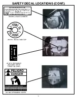
Страница 5: ...FF the engine before servicing cleaning or adding fuel Failure to comply could result in seriĆ ous bodily injury CAUTION UNLEADED GASOLINE 14781 14781 ON FUEL TANK 14774 ON OIL TANK CAP 14770 T H R O T T L E IDLE RUN 14770 ON HANDLE RATCHET STYLE THROTTLE ONLY AIR CLEANER INSTRUCTIONS CLEAN ELEMENT DAILY MORE OFTEN UNDER DUSTY CONDITIONS TAP ELEMENT LIGHTLY ON A FLAT SURFACE IF DUST DOES NOT DROP ...

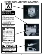
Страница 6: ...ING MOVING PARTS Make sure all guards and safety devices are in place Wear approved hearing protection foot protection eye protection and head protection SHUT OFF the motor before servicing or cleaning Failure to comply could result in seriĆ ous bodily injury CAUTION OPERATING INSTRUCTIONS 13534 1 Connect air supply hose Use Safety Clips 2 Open air supply hose valve on compressor 3 Squeeze actuato...

Страница 7: ...s equipment ROTATING MOVING PARTS Make sure all guards and safety devices are in place DO NOT RUN this machine in an enclosed area The engine produces carbon monoxide a POISONOUS GAS Wear approved hearing protection foot protection eye protection and head protection SHUT OFF the engine before servicing cleaning or addĆ ing fuel Failure to comply could result in serious bodily injury CAUTION Machin...

Страница 8: ... DITIONS TAP ELEMENT LIGHTLY ON A FLAT SURFACE IF DUST DOES NOT DROP OFF EASILY OR IF ELEMENT IS BENT OR CRUSHED REPLACE IT WARNING DO NOT OPERATE ENGINE WITHOUT AIR CLEANER ELEMENT INTERNAL DAMAGE WILL RESULT 06079 06079 ON AIR CLEANER 01064 B 01064 ON ENGINE 01060 ON AIR CLEANER 01326 SPRINGBOX COVER ...

Страница 9: ...ating this piece of equipment Keep unauthorized and untrained people away from this equipment ROTATING MOVING PARTS Make sure all guards and safety devices are in place DO NOT RUN this machine in an enclosed area The engine produces carbon monoxide a POISONOUS GAS Wear approved hearing protection foot protection eye protection and head protection SHUT OFF the engine before servicing cleaning or ad...

Страница 10: ...LY ON A FLAT SURFACE IF DUST DOES NOT DROP OFF EASILY OR IF ELEMENT IS BENT OR CRUSHED REPLACE IT WARNING DO NOT OPERATE ENGINE WITHOUT AIR CLEANER ELEMENT INTERNAL DAMAGE WILL RESULT 06079 06079 ON AIR CLEANER 14770 ON HANDLE RATCHET STYLE THROTTLE ONLY 01326 SPRINGBOX COVER 14770 T H R O T T L E IDLE RUN 14774 ON OIL TANK CAP ...

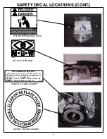
Страница 11: ... areas pushing down on handle will aid climbing ability Do not bear down with excessive weight on machine 6 Release actuator handle to stop 13534 ON VALVE BLOCK AIRAMMER ONLY 12203 ON VALVE BLOCK AIRAMMER ONLY 12203 Read the Operating Instructions before operating this piece of equipment Keep unauthorized and untrained people away from this equipment ROTATING MOVING PARTS Make sure all guards and ...

Страница 12: ...10 SAFETY DECAL LOCATIONS CONT AIRAMMER12213 12213 ON VALVE BLOCK TO START SQUEEZE ACTUATOR HANDLE TO STOP RELEASE 13538 13538 ON ACTUATOR HANDLE U S PATENT 5 340 233 13535 13535 ON VALVE BLOCK ...

Страница 13: ...nstall the same on machines previously sold 9 MBW INC is not responsible for any liability or damage or injury directly or indirectly from design material or operation of its products 10 Warranty card must be returned to MBW INC P O Box 440 Slinger Wisconsin 53086 0440 within 10 days after purchase assignment to a rental fleet or first use In England MBW UK LIMITED Bradley Fold Trading Estate Unit...

Страница 14: ... The locations and phone numbers of the Sales Branches are listed below Remember you own the best If repairs are needed use only MBW Inc parts purchased from Authorized MBW Inc Distributors Sales Branches 1 MBW Inc 250 Hartford Rd P O Box 440 Slinger WI 53086Ć0440 Phone 262 644Ć5234 FAX 262 644 5169 2 MBW Inc 2341 Pomona Rincon Rd Suite 106 Corona CA 92880 Phone 714 272Ć9989 FAX 714 272 9611 Great...

Страница 15: ...8 4500 20 4550 20 3 Percussion Rate blows minute 600Ć650 600Ć650 550 600 550 600 600Ć650 600Ć650 Travel Speed ft min m min 55 16 8 55 16 8 50 15 3 50 15 3 60 18 3 60 18 3 Compaction Depth in cm 22 56 22 56 24 61 23 58 24 61 24 61 Compaction Area sqft h sqm h 3025 280 3025 280 1000 93 1500 139 3300 307 3900 362 Engine Speed rpm 4300 4400 4000 4000 4400 4400 Fuel Capacity qts L 2 5 2 4 2 5 2 4 2 5 2...

Страница 16: ...perating Instructions and Parts Catalog for exploded view and parts identifications PARTS ORDERING MBW Inc parts are available worldwide and must be ordered through your local MBW Inc Distributor If you cannot locate an MBW Inc Distributor in your area refer to page 5 of this Manual locate the MBW Inc Sales Branch nearest you and call for assistance ALWAYS INCLUDE 1 Model and Serial Number of Mach...

Страница 17: ...GASOLINE POWERED RAMMERS WITH ROBIN EC12 ENGINES ONLY FUEL SUPPLY The oil injected engines on gasoline powered MBW Inc rammers use an unleaded gasoline mixture of 32 1 for a break in period After running the machine for a time check to see if the engine is consuming 2Ćcycle oil from the oil tank If the engine is consuming oil from the tank you can use just unleaded gasoline in the fuel tank NOTE A...

Страница 18: ...BW AIRAMMERS require a compressed air supply of at least 85 cfm cubic feet per minute at 110 psi pounds per square inch The air supply must be provided on a continuous basis i e Check the compressor pressure gauge while the rammer is running Peak compaction performance will not be achieved if the air supply is inadequate MOTOR ICING If the rammer is operated for extended periods of time or is oper...

Страница 19: ... the stop button on the side of the blower housing or turn the switch on the blower housing to OFF 4 Close fuel valve STOP THE ENGINE BEFORE Adding fuel or oil Leaving equipment unattended even if only for a minute Making any repairs or adjustments PNEUMATIC POWERED MODELS STARTING 1 Connect the air compressor supply hose to the airammer USE SAFETY CLIPS 2 Open the air supply hose valve on the com...

Страница 20: ...ons and Parts List ENGINE LUBRICATION Robin EC12 oil injected 1 The EC12 twoĆcycle engine is lubricated by the twoĆcycle oil from a separate oil tank Use a 32 1 gas to oil mixture for a breakĆin period of 8 hours After breakĆin use only unleaded gasoline in the fuel tank provided the engine is consuming oil from the oil tank 2 The oil tank is equipped with a filtering screen built into the elbow o...

Страница 21: ...hile the rammer is running R270A R450A R451A require at least 75 cfm cubic feet per minute at 110 psi pounds per square inch MOTOR ICING If the rammer is operated for extended periods of time or is operated in high humidity conditions frost will form on the motor This is normal and will not harm the motor If the motor should freeze up from icing allow it to thaw before continuing usage Ensure that...

Страница 22: ...andle free from the Rammer PNEUMATIC RAMMERS 1 Disconnect the compressed air supply hose at the rammer handle valve block Ensure that air supply hoses have been depressurized before disconnecting 2 Disconnect the air hose at the pneumatic motor 3 Remove four 4 Socket Head Cap Screws Fig 7 23 and lift the Handle free from the Rammer MOTOR REMOVAL It is not necessary to remove the Handle to take the...

Страница 23: ...em See Figure 1 FIGURE 1 R374 R376 1 Remove the Socket Head Cap Screws Fig 8 40 from the top of the Guide Tube flange 2 Push the Bellows and Rubber Gasket down until the Flat Head Socket Screws are exposed Fig 8 29 Remove the flat head socket screws and Conical Lockwashers Fig 8 29 28 The conical washers may not be reused New conical washers must be used upon assembly 3 Push the Guide Tube Fig 10 ...

Страница 24: ...drum side This will relieve the pressure on the retaining ring 2 Press out Pinion 21 3 Pry out Seal 20 and replace 4 Remove Retaining Ring 9 5 Press out Bearing 7 CRANK GEAR REMOVAL 1 Slip a retaining ring pliers through the slot opening in the Crank Gear 6 and remove the Retaining Ring 9 See Figure 4 FIGURE 4 2 Remove the Hex Head Cap Screw 18 and Seal Washer 17 from front cover 3 Use a 3 8 in 10...

Страница 25: ...e Remove the six Hex Nuts and Lockwashers Fig 9 27 26 and remove the Shoe Fig 9 25 374 6 Remove four Deformed Locknuts Hex Nuts and Lockwashers Fig 10 29 28 27 reĆ move Shoe Fig 10 25 5 Lift Bellow Mount Fig 9 7 off Spring Box Fig 9 12 Remove and replace bellow mount OĆRing Fig 9 8 A separate bellow mount is not used on trench rammers SPRING BOX CAUTION Observe the WARNING LABEL Fig 9 24 on the Sp...

Страница 26: ...efore installing the Gearbox to the Lower System install a new Gasket Fig 7 26 on the top of the Lower System 10 Torque the four Socket Head Cap Screws Fig 7 29 holding the Gearbox to the Lower System to 60 ft lbs 81 N m LOWER SYSTEM ASSEMBLY 1 The Elastic Stop Nut Fig 9 18 must be replaced and torqued to 100 ft lbs 135 N m 2 Lightly grease the OĆRing groove in the Cover Fig 9 20 before installing...

Страница 27: ...ller 07575 Kit R270 Robin Air Cleaner EC10 07694 Kit R270 Shoe Width Extension 14 07745 Kit Breakerless Ignition Robin EC10D 07747 Kit Robin EC10D TCI unit Replacement 07790 Kit R270C 14 Wide Handle 12230 Kit Governor Wrench TCS Motor 12247 Kit Swivel Airammer 12248 Kit Filter Lubricator Airammer TORQUE CHART TIGHTENING TORQUE In cast iron or steel SIZE GRADE 2 GRADE 5 10Ć24 32 in lb 40 in lb 10Ć3...

Страница 28: ...id between the Spring Box and Guide Tube replace the Bushings Hardware Torque all bolts after the first eight hours of operation and check evĆ ery 25 hours OĆRings and Seals Replace at every overhaul or teardown Use MĆBĆW OĆRing and Seal Kit 06472 Oil Screen Clean or Replace Oil Screen every 300 hours or 1 year Robin EC12D Oil Line Replace Oil Line every year Robin EC12D Pinion Replace if teeth ar...

Страница 29: ...27 FIGURE 7 270 450 451 GEARBOX ...

Страница 30: ...RBOX S N 2717321 ABOVE 270 4511899 ABOVE 450 451 1 20 06274 SEAL OIL 1 21 06249 PINION 1 22 07351 SHOCKMOUNT R270 ONLY 2 11530 SHOCKMOUNT R450 R451 ONLY 2 06302 SHOCKMOUNT R270 PRIOR TO SERIAL 2700929 NOT SHOWN 2 23 F051810SCS SOCKET HEAD CAP SCREW 5 16 18 X 1 1 4 4 F051818SCS SOCKET HEAD CAP SCREW 5 16 18 X 2 1 4 USE WITH 06302 4 24 25 F0618SPP SOCKET PIPE PLUG 3 8 NPT 1 26 06925 GASKET 1 27 0630...

Страница 31: ...29 FIGURE 8 374 376 GEARBOX ...

Страница 32: ...1 19 06169 GEARBOX S N BELOW 3700440 1 19 15872 GEARBOX S N 3700440 ABOVE 1 20 06274 SEAL OIL 1 21 06249 PINION 1 22 11530 SHOCKMOUNT 2 23 F051810SCS SOCKET HEAD CAP SCREW 5 16 18 X 1 1 4 4 24 07172 WASHER HIGH COLLAR 4 25 F0618SPP SOCKET PIPE PLUG 3 8 NPT 1 26 06925 GASKET 1 27 06304 PISTON PIN 1 28 11689 LOCKWASHER 1 2 CONICAL 4 29 F081310FSS FLAT HEAD SOCKET SCREW 1 2 13 X 1 1 4 4 30 06908 TUBE...

Страница 33: ...31 FIGURE 9 270 450 451 LOWER SYSTEM ...

Страница 34: ... 06179 PISTON 1 18 06257 HEX NUT 7 8 14 ELASTIC LOCK 1 19 06237 O RING 1 20 06173 COVER 1 21 F042005FSS FLAT HEAD SOCKET SCREW 1 4 20 X 5 8 3 22 06457 GAGE VIEW 1 23 F0227SPP SOCKET PIPE PLUG 1 8 27 1 24 01326 DECAL WARNING SPRING TENSION 1 25 07507 SHOE ALUMINUM 11 X 13 R270 R450 ONLY 1 03172 SHOE ALUMINUM 13 X 15 R451 ONLY 1 06159 SHOE CAST IRON 11 X 13 1 26 F07LW LOCKWASHER 7 16 6 27 F0714HN HE...

Страница 35: ...33 FIGURE 10 374 376 LOWER SYSTEM ...

Страница 36: ...06257 HEX NUT 7 8 14 ELASTIC LOCK 1 19 03136 O RING 1 20 02606 COVER 1 21 F042005FSS FLAT HEAD SOCKET SCREW 1 4 20 X 5 8 2 22 06457 GAGE VIEW 1 23 F0227SPP SOCKET PIPE PLUG 1 8 27 1 24 01326 DECAL WARNING SPRING TENSION 1 25 07956 SHOE ASSEMBLY 4 X 18 R374 ONLY INCLUDES ITEM 26 1 07960 SHOE ASSEMBLY 6 X 18 R376 ONLY INCLUDES ITEM 26 1 26 03158 STUD 1 2 13 X 3 4 27 08504 LOCKWASHER 1 2 HIGH COLLAR ...

Страница 37: ...35 FIGURE 11 270 450 451 HANDLE ...

Страница 38: ... 2 13 06903 BUSHING 2 14 07906 THROTTLE ASSEMBLY INCLUDES ITEM 20 S N BELOW 2717551 270 AND 4511933 450 451 1 14 14715 THROTTLE ASSEMBLY INCLUDES ITEM 20 S N 2717551 ABOVE 270 4511933 ABOVE 450 451 1 15 F03LW LOCKWASHER 10 1 16 F033210RMS ROUND HEAD MACHINE SCREW 10 32 X 1 1 4 1 17 07921 CASING 1 18 07920 WIRE THROTTLE 1 19 F0332HN HEX NUT 10 32 1 20 07916 FERRULE NOT SHOWN 21 07750 FUEL LINE ASSE...

Страница 39: ...37 FIGURE 12 STANDARD HANDLE OIL INJECTED ONLY ...

Страница 40: ... HEAD MACHINE SCREW 10 32 X 1 1 4 1 17 07887 THROTTLE CABLE CASING NOT SHOWN 1 18 07888 WIRE THROTTLE NOT SHOWN 1 19 F0332HN HEX NUT 10 32 1 20 07750 FUEL LINE ASSEMBLY INCLUDES ITEMS 22 23 29 1 21 15016 CLAMP FUEL LINE HOSE 2 22 01045 FUEL FILTER 1 23 01052 CLAMP FUEL LINE HOSE 4 24 14725 OIL TANK ASSEMBLY INCLUDES ITEMS 23 25 26 28 30 32 33 1 25 14508 OIL TANK 1 26 14714 OIL CAP 1 27 14925 CLAMP...

Страница 41: ...39 FIGURE 13 374 376 HANDLE ...

Страница 42: ...ASTIC 2 13 06903 BUSHING 2 14 07906 THROTTLE ASSEMBLY INCLUDES ITEM 20 S N BELOW 3700441 1 14 14715 THROTTLE ASSEMBLY INCLUDES ITEM 20 S N 3700441 ABOVE 1 15 F03LW LOCKWASHER 10 1 16 F033210RMS ROUND HEAD MACHINE SCREW 10 32 X 1 1 4 1 17 07887 CASING 1 18 07888 WIRE THROTTLE 1 19 F0332HN HEX NUT 10 32 1 20 07916 FERRULE 1 21 07750 FUEL LINE ASSEMBLY INCLUDES ITEMS 23 24 1 22 07865 PIN SNAPPER 1 4 ...

Страница 43: ...41 FIGURE 14 LO PROFILE HANDLE 1 3 6 10 11 13 11 9 ...

Страница 44: ... THROTTLE ASSEMBLY INCLUDES ITEM 20 S N BELOW 2717551 270 AND 4511933 450 451 1 14 14715 THROTTLE ASSEMBLY INCLUDES ITEM 20 S N 2717551 ABOVE 270 4511933 ABOVE 450 451 1 15 F03LW LOCKWASHER 10 1 16 F033210RMS ROUND HEAD MACHINE SCREW 10Ć32 x 1Ć1 4 1 17 07887 CASING 1 18 07888 WIRE THROTTLE 1 19 F0332HN HEX NUT 10Ć32 1 20 07916 FERRULE 1 21 07750 FUEL LINE ASSEMBLY INCLUDES ITEM 23 24 1 22 13513 FU...

Страница 45: ...43 FIGURE 15 LO PROFILE HANDLE OIL INJECTED ONLY ...

Страница 46: ...033210RMS ROUND HEAD MACHINE SCREW 10 32 X 1 1 4 1 17 07888 THROTTLE CABLE CASING NOT SHOWN 1 18 07887 WIRE THROTTLE NOT SHOWN 1 19 F0332HN HEX NUT 10 32 1 20 07750 FUEL LINE ASSEMBLY INCLUDES ITEMS 22 23 29 1 21 15016 CLAMP HOSE 2 22 01045 FILTER 1 23 01052 CLAMP HOSE 4 24 14725 OIL TANK ASSEMBLY INCLUDES ITEMS 23 25 26 28 30 32 33 1 25 14508 OIL TANK 1 26 14714 OIL CAP 1 27 14925 CLAMP VALVE 1 2...

Страница 47: ...45 FIGURE 16 AIRAMMER HANDLE 1 2 3 4 5 6 7 8 9 10 15 11 12 16 14 17 18 090 100 13 5 17 10 CF USA 28 29 30 31 32 33 34 TO AIRAMMER FROM COMPRESSOR 26 ...

Страница 48: ... 1 17 F042804SSSN SOCKET HEAD SET SCREW 1 4 28 X 1 2 NYLOC 1 18 11601 BLOCK VALVE AIRAMMER 1 19 11996 ASSEMBLY AIRAMMER HANDLE INCLUDES ALL ABOVE 1 20 F051808FWS FLANGE WHIZ LOCK SCREW 5 16 18 X 1 NOT SHOWN 4 21 F0518FLN FLANGE LOCKNUT 5 16 18 DEFORMED NOT SHOWN 4 22 07351 SHOCKMOUNT 270 374 6 450 1 AIRAMMER ONLY NOT SHOWN 2 AIRAMMER KITS SWIVEL FILTER LUBRICATOR KITS 26 12247 KIT SWIVEL AIRAMMER ...

Страница 49: ...47 FIGURE 17 ROBIN ENGINE ...

Страница 50: ...0 F061608FWS FLANGE WHIZ LOCK SCREW 3 8 16 X 1 2 11 06747 SOCKET HEAD CAP SCREW M8 X 25 mm 2 12 F05LW LOCKWASHER 5 16 2 13 06446 GASKET 1 14 07565 BASE 1 15 07570 TABLOCK 1 16 07563 HEX HEAD CAP SCREW M5 X 10 mm SLOTTED 3 17 K230840 ELEMENT 1 18 07566 COVER 1 19 F0420EWN WINGNUT 1 4 20 ELASTIC 1 20 21 07921 CASING 270 450 451 1 07887 CASING 374 376 1 22 07920 WIRE THROTTLE 270 450 451 1 07888 WIRE...

Страница 51: ...49 FIGURE 18 ROBIN OIL INJECTED ENGINE ...

Страница 52: ... 14600 ENGINE ROBIN EC12 1 7 14946 CLAMP OIL LINE 1 2 1 8 15192 CLAMP OIL LINE 1 2 1 9 15194 HEX HEAD CAP SCREW M8 1 25 X 14mm 1 10 F05LW LOCKWASHER 5 16 1 11 F06LW LOCKWASHER 3 8 NOT SHOWN 4 12 F061614HCS HEX HEAD CAP SCREW 3 8 16 X 1Ć3 4 MTG BOLT NOT SHOWN 4 13 157Ć32600Ć07 ELEMENT 1 14 161Ć32635Ć18 COVER 1 15 161Ć35201Ć01 GASKET 1 16 161Ć30101Ć11 MUFFLER 1 FOR A COMPLETE ENGINE BREAKDOWN CONTAC...

Страница 53: ...51 FIGURE 19 LO PROFILE ROBIN ENGINE ...

Страница 54: ... PUMP 1 9 F042006HCS HHCS 1 4Ć20 x 3 4 LG 2 10 F0420HN NUT HEX 1 4Ć20 2 11 F04LW LOCKWASHER 1 4 2 12 10119 BOLT SHCS M8 x 30 mm 2 13 F05SW PLAINWASHER 5 16 2 14 F05LW LOCKWASHER 5 16 2 15 02293 HOSE FUEL 1 16 15783 HOSE 3 32 I D VACUUM LINE 1 17 01035 HOSE FUEL 1 18 01052 CLAMP HOSE 4 19 F04PW PLAINWASHER 1 4 AS NEEDED 12 20 F042008HCS HHCS 1 4 20 X 1 LG AS NEEDED 2 21 14979 CLAMP HOSE 5 32 2 FOR ...

Страница 55: ...53 FIGURE 20 AIRAMMER MOTOR 2 6 5 4 3 1 9 8 7 TO VALVE BLOCK TO MOTOR INLET ...

Страница 56: ...MER 1 2 12190 FLANGE TCS 1 3 F04HCLW LOCKWASHER HIGH COLLAR 1 4 3 4 F042012SCS SOCKET HEAD CAP SCREW 1 4 20 X 1 1 2 3 5 F06LW LOCKWASHER 3 8 4 6 F061610HCS HEX HEAD CAP SCREW 3 8 16 X 1 1 4 4 7 12189 MOTOR PNEUMATIC 1 8 12199 FITTING ELBOW PARKER 10 CTX S 1 9 10099 HOSE 5 8 X 22 1 ...

Отзывы:

Похожие инструкции для R270R