background image

11 


3-5 Dissembling and Reassembling a Stapler Unit 

(Removing the staples that are stuck)   

 
1. Following the steps in

 3-4 Replacing the Staple Level Sensor

, remove the sensor.   

 
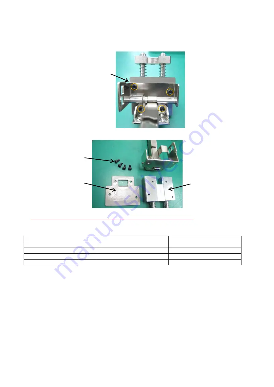
2. Remove the four hexagonal hole screws.   


3. After disassembly, remove all the staples.   


4. After the removal, take the reverse steps to reassemble the product.   

    When inserting the connector into the sensor, be careful not to bend the pin. 

    Refer to 

3.6 Adjusting the Stapler Unit Head

.   

 
List of Components 
No. 

Name 

Qty. 

01-001 

Stapler Unit 

221 

Base Block 

226 

Plate 

HS3x6 

Inner Hexagonal Hole Screw   


4-HS3x6 

226 

[Plate] 

4-HS3x6 

221 [Base Block] 

Содержание iBOOKLET

Страница 1: ...MBM iBOOKLET Oct 24 2016 MBM Corporation Ver A_1 Service Manual ...

Страница 2: ...the Staple Level Sensor 10 3 5 Dissembling and Reassembling a Stapler Unit Removing the staples that are stuck 11 3 6 Adjusting the Stapler Unit Head 12 3 7 Replacing and Cleaning Clincher Pieces 14 3 8 Adjusting the Clincher Position 15 3 9 Adjusting the Cushion Piece 16 3 10 Adjusting the Belt Tension 18 3 11 Replacing the Circuit Board 20 3 12 Replacing the Control Panel 21 3 13 Replacing a Joi...

Страница 3: ...3 3 26 Replacing the Wind Up Roller 43 4 Adjusting the Program 46 4 1 Maintenance Mode 46 4 2 Installing Program Writing Software 48 4 3 Upgrading the Program 52 ...

Страница 4: ...se an electric shock or fire Do not use a damaged power cord Do not process the power cord Do not put anything heavy on the power cord Keep the AC inlet at least 8 cm from the wall Failure to follow these instructions could cause an electric shock or fire Warning Do not use the product when it is acting abnormally such as emitting smoke foul odors or noises Doing so may cause an electric shock or ...

Страница 5: ... staples 1 Replacement of the sensor is recommended 3 4 Replacing the Staple Level Sensor 2 Trouble with Paper 1 Paper is slowly fed 1 Adjust the tension of the belt 3 10 Adjusting the Belt Tension 2 Paper is folded at an inappropriate position 1 Adjust the tension of the belt 3 10 Adjusting the Belt Tension 2 Adjust the folding position 4 1 Maintenance Mode 3 Replacement of the cushion piece is r...

Страница 6: ...eck if there is a plate between the push up upper sensor and the stapler lower sensor 3 19 Replacing Sensors 4 If the clincher motor does not operate when the clincher is in the loop mode check the motor 3 22 Replacing the Clincher Motor 5 If the clincher moves beyond its lower limit check the clincher sensor 3 19 Replacing Sensors 6 If the paper feed motor is not operational check the paper senso...

Страница 7: ...ocked screw becomes unfastened remove the screw lock and apply the screw lock again at the time of reassembly The Threebond 1401B is recommended Prior to unfastening any position adjusted screw record its original position to ensure that it is at refastened at the original position in the reassembly process Small Pan Head Screw M Flat Washer medium W Washer Equipped Screw small NC Wing Bolt WB Hex...

Страница 8: ...er R 3 NB3x8 400 Front Cover 3 NB3x8 407 Guide Cover R 504 Paper Size Sticker 403 Upper Cover R Trace the injection through the gate on the right side 424 Inside Cover R 2 S3x6 406 Side Cover L 3 NB3x8 Front 504 Power Switch Sticker 3 NB3x8 503 Company Logo Sticker 423 Inside Cover F 2 S3x6 404 Upper Cover L 2 pieces of 425 PIN 2 pieces of E3 Fix the E shaped ring from the outside 2 E3 2 pieces of...

Страница 9: ...x6 Washer Equipped Screw medium 12 S3x6 Small Countersunk Head Screw 6 E3 E Shaped Ring 4 3 2 Replacing the Stapler Units 1 Remove the two cable assemblies 1 Then while holding the stapler unit remove the wing bolt 2 After the replacement take the reverse steps to reassemble the product When inserting a connector to the sensor be careful not to bend the pin List of Components No Name Qty 104 Cable...

Страница 10: ...t 1 225 Knock Pin 1 3 4 Replacing the Staple Level Sensor 1 Following the steps in 3 2 Replacing the Stapler Units remove the stapler unit 2 Remove the sensor 3 After the replacement take the reverse steps to reassemble the product When inserting the connector into the sensor be careful not to bend the pin List of Components No Name Qty 01 001 Stapler Unit 1 102 Sensor 1 01 001 Stapler Unit 225 Kn...

Страница 11: ...le screws 3 After disassembly remove all the staples 4 After the removal take the reverse steps to reassemble the product When inserting the connector into the sensor be careful not to bend the pin Refer to 3 6 Adjusting the Stapler Unit Head List of Components No Name Qty 01 001 Stapler Unit 1 221 Base Block 1 226 Plate 1 HS3x6 Inner Hexagonal Hole Screw 4 4 HS3x6 226 Plate 4 HS3x6 221 Base Block...

Страница 12: ...f the rail 4 Unfasten four screws and adjust the rail position to ensure that the left part space and the right part space of the knock pin are evenly inserted Fix the rail in the state in which it is not forced downwards but naturally placed Check that the inserted knock pins are not shaky and can be moved smoothly F3x12 225 Knock Pin 229 Rail Adjust the rail to make sure that the left part and t...

Страница 13: ... make it easy to attach the slider tension spring List of Components No Name Qty 102 Sensor 1 225 Knock Pin 1 232 Slider 1 229 Rail 1 F3x12 Small Flat Head Screw 1 TR3x4 Small Truss Head Screw 4 An example of a jig Fasten the small flat head screw to the half of the depth and catch the spring using the jig Jig ...

Страница 14: ...rse steps to reassemble the product After the replacement perform a clinching trial If there is any problem with the shape of the staple reattach the piece in the opposite direction Cleaning Clincher Pieces Clean the depressed part of the piece with a swab or a soft cloth List of Components No Name Qty 01 005 Piece 5 S3x4 Small Countersunk Head Screw 10 5 pieces of 275 5 pieces of 2 S3x4 Reverse t...

Страница 15: ...ss on the rear side 3 Loosen the hexagonal hole screws and three screws without detaching them Then move the upper screw positions to adjust the front rear position of the clincher Next refasten the screws Perform the same process on the opposite site as well 413 Reinforcement S 4 NC3x6 HS4x12 Keep it loose until the adjustment is finished 3 M4x8 The front rear position is adjusted at the position...

Страница 16: ...Components No Name Qty 413 Reinforcement S 2 NC3x6 Washer Equipped Screw small 8 M4x8 Small Pan Head Screw 6 HS4x12 Inner Hexagonal Hole Screw 2 3 9 Adjusting the Cushion Piece 1 Following the steps in 3 1 Replacing the Outer Covers remove the side cover L 2 Unfasten four screws to remove the main unit bottom plate Adjusting the front rear position of the clincher piece When the piece is closer to...

Страница 17: ...smoothly List of Components No Name Qty 206 Main Unit Bottom Plate 1 299 Timing Belt 1 426 Cushion Piece 1 427 Spring 1 429 Spacer 1 430 Washer 1 M4x8 Small Pan Head Screw 4 F3x12 Small Flat Head Screw 1 426 Cushion Piece F3x12 426 Cushion Piece F3x12 Catch the spring on this screw Fasten F3x12 while pulling the timing belt to ensure that the cushion piece is movable and attach a screw lock 299 Ti...

Страница 18: ...de cover R 2 Unfasten three screws to remove the lower bracket Perform the same process on the opposite side 3 Unfasten four screws to remove the main unit bottom plate 4 Unfasten four screws to remove the stay Perform the same process on the opposite side 206 Main Unit Bottom Plate 4 M4x8 411 Lower Bracket 3 M3x6 205 Stay 4 M4x8 Do not unfasten this screw ...

Страница 19: ...Components No Name Qty 411 Lower Bracket 2 206 Main Unit Bottom Plate 1 205 Stay 1 300 Bracket 1 299 Timing Belt 1 298 Bracket 1 113 Paper Feed Motor 1 M3x6 Small Pan Head Screw 3 M4x8 Small Pan Head Screw 14 Set the tension to the level at which the two parts of the timing belt do not come into contact when they are gently pinched between two fingers Use this screw for adjustment Fix it while pul...

Страница 20: ...take the reverse steps to reassemble the product Check if the signs on the tags are identical between the circuit board and the wiring Nothing is connected to J6 If writing a program is required refer to 4 3 Upgrading the Program List of Components No Name Qty 101 Circuit Board 1 501 1 Control Panel metric 1 501 2 Control Panel inches 1 F3x6 Small Flat Head Screw 8 101 Circuit Board 8 F3x6 501 1 C...

Страница 21: ...e use of alcohol Then attach a new control panel exactly on the area of the board indicated within the white rectangle Be sure not to make any bubbles 4 After the replacement take the reverse steps to reassemble the product List of Components No Name Qty 101 Circuit Board 1 501 1 Control Panel metric 1 501 2 Control Panel inches 1 101 Circuit Board 501 1 Control Panel metric or 501 2 Control Panel...

Страница 22: ...ch 5 Unfasten the left and right hexagonal hole screws to remove the guide shaft from the joint arm and then remove the joint arm Take note of the relationship between the installation positions of the screws and the flat washers Cut the cable tie When binding fasten the tie at about 120 mm from the ends of cables 109 Connector Catch Pay attention to its position and orientation 240 Joint Arm Cabl...

Страница 23: ... attached and repeat it until the problem is resolved List of Components No Name Qty 240 Joint Arm 1 109 Connector Catch 1 243 Guide Shaft 2 HS4x12 Inner Hexagonal Hole Screw 2 LW4 Flat Washer small 2 Loosen the left and right hexagonal hole screws to adjust the position Paper insertion direction The joint arm is displaced leftwards The joint arm is displaced rightwards The joint arm is at the cor...

Страница 24: ...t take the reverse steps to reassemble the product Incorrect wiring and loose connections may cause failures or fires Be sure to check the terminal to which each cable should be connected List of Components No Name Qty 206 Main Unit Bottom Plate 1 115 Power Supply Unit 1 NC3x10 Washer Equipped Screw small 2 M4x8 Small Pan Head Screw 4 115 Power Supply Unit 2 NC3x10 Disconnect five cables Connectio...

Страница 25: ... 3 Unfasten two screws to remove the inlet 4 After the replacement take the reverse steps to reassemble the product List of Components No Name Qty 118 Inlet 1 S3x6 Small Countersunk Head Screw 2 118 Inlet 118 Inlet 2 S3x6 Three cables Green Yellow Black White Connection to the Inlet Terminals Color Black Green Yellow White Terminal L GND N ...

Страница 26: ...assemble the product List of Components No Name Qty 115 Power Supply 1 116 Switch Unit 1 117 Button 1 118 Inlet 1 115 Power Supply Unit Connection to the terminals of the power supply unit Color Black White Terminal L N Connection to the terminals of the inlet terminals Color Black White Terminal L N 116 Switch Unit The ON sign at the lower position 117 Button Internal Gear Washer Hexagonal Nut He...

Страница 27: ...J18 from the circuit board 3 Cut the cable tie that binds cable J18 to remove the spiral tube 4 Unfasten two screws to remove the cover switch together with the sensor cover 5 Unfasten two screws to remove the sensor cover Connector J18 コネクタ Cable Tie Spiral Tube 2 M3x6 422 Sensor Cover 2 M3x25 SW3 W3 N3 120 Cover Switch 422 Sensor Cover ...

Страница 28: ...to check if the switch operates without fail when the cover is slowly closed List of Components No Name Qty 120 Cover Switch 1 422 Sensor Cover 1 M3x6 Small Pan Head Screw 2 M3x25 Small Pan Head Screw 2 W3 Flat Washer medium 2 SW3 Spring Washer 2 N3 Hexagonal Nut 2 Fix with the screw pushed upwards ...

Страница 29: ...m plate 3 Following the steps in 3 9 Replacing the Cushion Piece remove the cushion piece 4 Unfasten three screws to remove the paper feeder Be careful not to lose the four ball bearings 5 Unfasten the screw to remove the paper sensor 4 pieces of 333 Ball Bearing 206 Main Unit Bottom Plate 4 M4x8 3 SF3x20 SW3 LW3 Paper Feeder TR3x6 103 Paper Sensor Connect Cable J11 ...

Страница 30: ... 210 Top Plate 1 290 Plate 1 297 Bracket 1 M4x8 Small Pan Head Screw 4 SF3x20 Small Slotted Flat Head Screw 3 SW3 Spring Washer 3 LW3 Flat Washer small 3 TR3x6 Truss Head Screw 1 291 Slider Push the slide the ball bearings and the screw towards the top plate Be careful of the slider orientation The photo shows the view from the reverse side 210 Top Plate Mount the slider Pay attention to its orien...

Страница 31: ... up sensor above and the stapler sensor below Replacing the Clincher Sensor 1 Remove the clincher sensor If the plate interferes unfasten the screws to remove it as well Push Up Upper Sensor 102 Sensor Connect Cable J8 Stapler Lower Sensor below 102 Sensor Connect Cable J7 245 Plate At the time of reassembly fasten it in its original position 2 NC3x6 Clincher Sensor 102 Sensor Connect Cable J12 2 ...

Страница 32: ...it 3 After the replacement take the reverse steps to reassemble the product When inserting a connector to the sensor be careful not to bend the pin List of Components No Name Qty 285 Plate 1 206 Main Unit Bottom Plate 1 102 Sensor 4 NC3x6 Washer Equipped Screw 4 M4x8 Small Pan Head Screw 4 206 Main Unit Bottom Plate 4 M4x8 Paper Feed Sensor 102 Sensor Connect Cable J1 ...

Страница 33: ...ove the front cover the rear cover and the side cover R 2 Unfasten four screws to remove the main unit bottom plate 3 Disconnect connector J2 from the circuit board 4 Cut the cable tie that binds cable J2 from the motor to the circuit board Connector J2 Cable Tie 206 Main Unit Bottom Plate 4 M4x8 ...

Страница 34: ... 1 248 Drive Gear 1 110 Stapler Motor 1 507 Lithium Grease M4x8 Small Pan Head Screw 4 NC4x15 Washer Equipped Screw 4 SS5x5 Set Screw 2 LW4 Flat Washer small 12 110 Stapler Motor 248 Drive Gear 2 SS5x5 4 NC4x15 12 LW4 Stack three washers in each of the four positions 4 NC4x15 The way in which the motor is removed Greasing Position Apply 507 Lithium Grease onto all of the gears Use grease at NLGI N...

Страница 35: ...onnect connector J4 from the circuit board 3 Cut the cable tie that binds cable J4 from the motor to the circuit board 4 Remove the E shaped ring and the gears Pay attention to attachment of grease Remove only the components indicated with arrows Connector J4 Cable Tie 264 Gear E3 265 Gear Gear 264 has a D shaped center hole Gear 265 has a round center hole ...

Страница 36: ...ear Fixing Plate 1 111 Wind Up Motor 1 506 Grease for Plastics NC3x6 Washer Equipped Screw small 6 E3 E Shaped Ring 1 111 Wind Up Motor 6 NC3x6 Some gear fixing plates are shaped like this Greasing Positions 506 Grease for Plastics Apply it to five positions on the gears Use grease at NLGI No 2 AZ s 738 is recommended 270 Gear Fixing Plate At the time of reassembly pay attention to the orientation...

Страница 37: ...crew to remove the gear Then unfasten four screws to remove the motor Pay attention to attachment of grease 5 After the replacement take the reverse steps to reassemble the product List of Components No Name Qty 283 Gear 1 112 Clincher Motor 1 507 Lithium Grease NC3x6 Washer Equipped Screw small 4 SS4x4 Set Screw 1 Connector J3 Cable Tie 283 Gear SS4x4 112 Clincher Motor 4 NC3X6 Greasing Positions...

Страница 38: ...nnector J5 from the circuit board 3 Cut the cable tie that binds cable J5 from the motor to the circuit board 4 Unfasten four screws to remove the paper feed motor together with the bracket 5 Unfasten four screws to remove the bracket Cable Tie Connector J5 4 S3x8 SW3 W3 298 Bracket 113 Paper Feed Motor 298 Bracket 113 Paper Feed Motor 4 NC3x5 Do not remove the pulley ...

Страница 39: ...e product For adjustment of the timing belt refer to 3 10 Adjusting the Belt Tension List of Components No Name Qty 113 Paper Feed Motor 1 298 Bracket 1 S3x8 Small Countersunk Head Screw 4 SW3 Spring Washer 4 W3 Flat Washer medium 4 NC3x5 Washer Equipped Screw small 4 ...

Страница 40: ...cket Perform the same process on the opposite side 3 Following the steps in 3 9 Adjusting the Cushion Piece remove the cushion piece 4 Unfasten four screws to remove the paper feed motor together with the bracket 5 Unfasten four screws to remove the stay Perform the same process on the opposite side 4 S3x8 SW3 W3 298 Bracket 113 Paper Feed Motor 411 Lower Bracket 3 M3x6 205 Stay 4 M4x8 Do not unfa...

Страница 41: ...3 10 Adjusting the Belt Tension to adjust the tension of the belt To reassemble the cushion piece refer to 3 18 Replacing the Paper Sensor List of Components No Name Qty 411 Lower Bracket 2 298 Bracket 1 113 Paper Feed Motor 1 205 Stay 1 210 Top Plate 1 294 Bracket 1 299 Timing Belt 1 M3x6 Small Pan Head Screw 6 M4x8 Small Pan Head Screw 14 S3x8 Small Countersunk Head Screw 4 SW3 Spring Washer 4 W...

Страница 42: ...ront cover and the rear cover 2 Lift up the upper cover R and the paper guide R at the same time to remove them 3 Remove the paper 4 After finishing the removal take the reverse steps to reassemble the product List of Components No Name Qty 403 Upper Cover R 1 416 Paper Guide R 1 403 Upper Cover R 416 Paper Guide R ...

Страница 43: ...pward on the upper cover R and the paper guide R at the same time to remove them 4 Remove the E shaped ring two types of gears and the gear fixing plates Pay attention to the attachment of grease Remove the only components indicated with arrows 5 Unfasten eight screws to remove the guide cover R and the axis bracket together Then remove the reinforcement S 407 Guide Cover R 418 Axis Bracket 412 Re...

Страница 44: ...ile spreading the case horizontally pull upward on the two rollers to remove them 404 Upper Cover L 4 NC3x6 417 Cover L 414 Paper Guide L 4 NC3x6 On the back side of the metal plate HS4x12 LW4 Several flat washers may be inserted for height adjustment purposes 317 Presser NC3x5 Likewise on the opposite side Two pieces of 313 Ball Bearing Likewise on the opposite side 243 Guide Shaft Lower it to re...

Страница 45: ... 313 Ball Bearing 4 01 006 Joint Arm 1 243 Guide Shaft 2 01 008 Wind Up Roller 2 316 Collar 4 266 Spring 2 506 Plastic Grease NC3x5 Washer Equipped Screw small 2 NC3x6 Washer Equipped Screw small 16 HS4x12 Inner Hexagonal Hole Screw 2 LW4 Flat Washer small 2 E3 E Shaped Ring 2 E6 E Shaped Ring 4 Two pieces of 260 Wind Up Roller 2 E6 266 Spring Two pieces of 16 Collar Perform the same process on th...

Страница 46: ...1 to 14 are displayed As the values change there is a brief beep When the value turns 14 with a long beep the function process is finished and the product will automatically restart The sensitivity adjustment is conducted automatically In the course of the adjustment do not touch the control panel Function 2 Switching between metric and inch measurements This function switches between metric and i...

Страница 47: ...he product will automatically restart Function 6 Freely operating individual motors This function allows you to freely move the paper feed motor the stapler motor the clincher motor and the wind up motor according to the rotation direction and the designated output However only one of the motors can be operated at a time Select the motor to be operated Free The paper feed motor ー B5 or Letter The ...

Страница 48: ...Windows 7 Professional 1 Select the disk that comes with the writer kit on the computer Double click setup exe in the MPLAB_IDE_8_90 folder The computer will start preparations for installation 2 When the window shown below appears click Next 3 Select I accept the and click Next 4 Select Complete and click Next ...

Страница 49: ...49 5 Click Next 6 Select I accept the and click Next 7 Select I accept the and click Next ...

Страница 50: ...50 8 Click Next and the installation process will start 9 Wait until the installation process is complete 10 Click Finish ...

Страница 51: ...51 11 If the window shown below appears click the X in the upper right corner to close it 12 Connect PICkit 3 to the computer using the accompanying USB cable The driver will automatically be installed ...

Страница 52: ...cuit board is accessible Connect the cable in the manner in which the red wire of the cable is located at position No 1 marked with the symbol of PICkit 3 and at Pin No 1 of Connector J16 on this product After the connection fasten the circuit board with screws while paying attention not to catch the cable between other components 3 Connect PICkit 3 to the computer using the USB cable that comes w...

Страница 53: ...mport to specify the HEX file to be written 9 In the MPLAB IDE window select Programmer and then Program to execute the writing process When Programming Verify complete is displayed the writing process is finished 10 The product will beep and the version number will be displayed for about three seconds Then the touchpad adjustment will automatically start After the automatic adjustment is finished...

Страница 54: ...ntact the distributor or a person in charge in our sales office to ask for a new one When you want to transfer this product to the next owner be sure to hand over this Instruction Manual along with the product If there is any label that becomes illegible or is about to peel off contact the distributor or a person in charge in our sales office to immediately replace it with a new one Service Manual...

Отзывы:

Похожие инструкции для iBOOKLET