


Installation and Operational Instructions for
ROBA-stop
®
-S brake Type 856. _ _ _ . _
Size 11
(B.8.3.1.GB)
19/11/2010 TK/KE/GC/SU
Chr. Mayr GmbH + Co. KG
Tel.: 08341 / 804-0
Eichenstraße 1
Fax: 08341 / 804-421
D-87665 Mauerstetten
http://www.mayr.de
Page 9 of 13
Germany
E-Mail:
Earthing Connection
The brake is designed for Protection Class I. This protection
covers not only the basic insulation, but also the connection of all
conductive parts to the PE conductor on the fixed installation. If
the basic insulation fails, no contact voltage will remain. Please
carry out a standardized inspection of the PE conductor
connections to all contactable metal parts!
Device Fuses
To protect against damage from short circuits, please add
suitable device fuses to the mains cable.
Switching Behaviour
The operational behaviour of a brake is to a large extent
dependent on the switching mode used. Furthermore, the
switching times are influenced by the temperature and the air
gap between the armature disk and the coil carrier (dependent
on the wear condition of the linings).
Magnetic Field Build-up
When the voltage is switched on, a magnetic field is built up in
the brake coil, which attracts the armature disk to the coil carrier
and releases the brake.
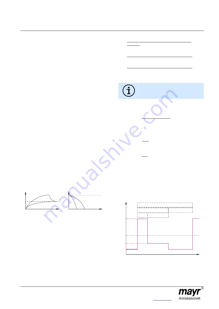
Field Build-up with Normal Excitation
If the magnetic coil is energised with nominal voltage, the coil
voltage does not immediately reach its nominal value. The coil
inductivity causes the current to increase slowly as an
exponential function. Accordingly, the build-up of the magnetic
field takes place more slowly and the braking torque drop (curve
1) is also delayed.
Field Build-up with Overexcitation
A quicker and safer drop in braking torque is achieved if the coil
is temporarily placed under a higher voltage than the nominal
voltage, as the current then increases more quickly. Once the
brake is released, it needs to be switched over to the nominal
voltage (curve 2). The relationship between overexcitation and
separation time t
2
is roughly indirectly proportional, meaning that
at doubled nominal voltage the separation time t
2
for release of
the brake is halved. The ROBA
®
-(multi)switch fast acting rectifier
and phase demodulator work on this principle.
Operation with overexcitation requires an inspection of :
- the required overexcitation time*
- as well as the RMS coil capacity** with a cycle frequency
higher than 1 cycle per minute.
* Overexcitation time t
over
Increased wear, and therefore an increasing air gap as well as
coil heating lengthen the separation time t
2
for the brake. For this
reason, at least double the separation time t
2
at nominal voltage
must be selected as overexcitation time t
over
on each brake size.
The spring forces also influence the brake separation times t
2
:
Higher spring forces increase the separation times t
2
and lower
spring forces reduce the separation times t
2
.
Spring force (braking torque adjustment) < 100 %
(Table 2):
The overexcitation time t
over
is less than the doubled
separation time t
2
.
Spring force (braking torque adjustment) = 100 %:
The overexcitation time t
over
equals the doubled separation time
t
2
.
Spring force (braking torque adjustment) > 100 %:
The overexcitation time t
over
is higher than the doubled
separation time t
2
.
** RMS coil capacity P
RMS
P
RMS
≤≤≤≤
P
nom
The coil capacity P
RMS
must not be larger than
P
nom
. Otherwise the coil may fail due to thermal
overload.
Calculations:
P
RMS
[W] RMS coil capacity dependent on switching frequency,
overexcitation, reductions in capacity and duty cycle
tot
hold
hold
over
over
RMS
t
t
P
t
P
P
×
+
×
=
P
nom
[W] Coil nominal capacity
(Catalogue information, Type tag)
P
over
[W] Coil capacity on overexcitation
nom
2
nom
over
over
P
U
U
P
×
=
P
hold
[W] Coil capacity at reduced capacity
nom
2
nom
hold
hold
P
U
U
P
×
=
t
over
[s] Overexcitation time
t
hold
[s] Time of operation with reduction in capacity
t
off
[s] De-energised time
t
tot
[s] Total time (t
over
+ t
hold
+ t
off
)
U
over
[V] Overexcitation voltage (bridge voltage)
U
hold
[V] Holding voltage (one-way voltage)
U
nom
[V] Coil nominal voltage
Time Diagram:
0
U
over
U
nom
U
hold
t
tot
t
off
t
on
t
hold
t
over
1
t
1
t
2
2
I
M
Braking torque path
M
nom
I
nom
Current path