Mayr ROBA-stop-S 856 Скачать руководство пользователя страница 12

Installation and Operational Instructions for  
ROBA-stop

®

-S brake  Type 856. _ _ _ . _ 

Size 11


(B.8.3.1.GB)


19/11/2010 TK/KE/GC/SU 

Chr. Mayr GmbH + Co. KG 

Tel.: 08341 / 804-0 


Eichenstraße 1 

Fax: 08341 / 804-421 


D-87665 Mauerstetten 

http://www.mayr.de 

Page 12 of 13 

Germany 

E-Mail: 

[email protected]


Braking Torque Adjustment (Figs. 1 to 3) 

The ROBA-stop-S brake Size 11 is set manufacturer-side to the 
nominal torque or to the braking torque stipulated on order. 
Braking torque adjustment is carried out by evenly removing or 
adding thrust springs (6 and 29) to the internal or external pole of 
the coil carrier (2) acc. Table 1. 
 

DANGER 

By removing the brake plate (16), the braking 
torque is nullified. Load movement must be 
prevented. 

 
Procedural Method: 

1.  Remove the brake plate (16) by loosening the hexagon 

head screws (17). Please observe the adjusting plates (28). 
If necessary, use the emergency release screws (9) as a 
removal aid. In this case, the screw plugs (10) with the 
copper sealing rings (11) must be unscrewed and screwed 
in again after brake plate (16) removal. 

2.  Remove the rotor (4). 

3.  Evenly loosen the 3 cap screws (7), which together with the 

collar bushings (8) hold (guide) the armature disk (5) axially, 
until the armature disk (5) can be removed. 
Danger! The armature disk is subject to spring pre-
tension!
 

4.  Remove abraded particles from the rotor and clean the 

brake. 
Do not use grease or oil! 

5.  Adjust the required braking torque by evenly removing or 

adding thrust springs (6 and 29) to/from the coil carrier (2) 
(see Table 1). 
One spring (6) at the internal pole equals 

102 Nm. 

One spring (29) at the external pole equals 

61 Nm. 


The thrust springs (6) at the internal pole of the 
coil carrier and the thrust springs (29) at the 
external pole of the coil carrier must not be 
interchanged (see Table 1). 

 
6.  Insert the armature disk (5). 

Please make sure that the two pins for actuating the 
microswitch situated next to each other protrude into 
the terminal box.
 

7.  Screw the armature disk (5) back on using cap screws (7) 

and added collar bushings (8). 
Observe the tightening torque of 85 Nm! 

8.  Push the rotor (4) back on. Check that the toothing moves 

easily. 


The rotor (4) must be placed onto the hub (1) 
so that the toothing remains engaged even after 
wear on the friction linings. 

 
9.  Mount the brake plate (16) again using hexagon head 

screws (17). Please make sure that the emergency release 
has the correct angular position (see Fig. 2).  
Do not damage the O-rings (18 and 19)!  
Observe the tightening torque of 46 Nm! 


Table 2: Spring Configuration 

Number of springs Ø 22 / 4,5 x 50 

at internal pole (Item 6) 

Torque on 

brakes 

[Nm] 

326 

428 

530 

632 

387 

489 

591 

693 

448 

550 

652 

754 

N

u

m

b

e

o

s

p

ri

n

g

s

 Ø

 1

9

 /

 3

,6


x

 3

8


a

e

x

te

rn

a

p

o

le

 (

It

e

m

 2

9

509 

611 

713 

815 


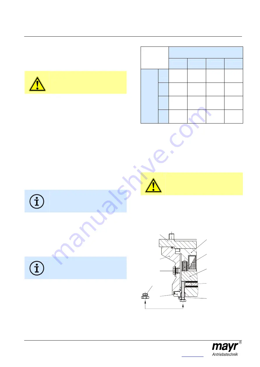
Emergency Release (Fig. 13) 

In case of malfunction or power failure, the brake remains 
closed; it cannot be released electrically. Emergency release can 
be carried out manually. 
 
1.  Unscrew the screw plugs (10) inc. the copper sealing rings 

(11). 

2.  Screw in both emergency release screws (9) evenly until the 

load on the motor starts moving. 

DANGER 

Caution with hoist drives! 
Actuating the emergency release nullifies the 
braking torque. 
Load crashes must be prevented. 

Interrupt the release procedure with individual stops (turning 
back the emergency release screws), so that there is no 
high load acceleration and brake heating occurrence. 

3.  After completing the emergency release procedure, unscrew 

both emergency release screws (9) again. 

4.  Screw the screw plugs (10) inc. the copper sealing rings 

(11) back in. 


Fig. 13 


29

4

9

5

2

3

16

31

12/13

10/11

Содержание ROBA-stop-S 856

Страница 1: ...n decimal points in this document are represented with a comma e g 0 5 instead of 0 5 Guidelines on the Declaration of Conformity A conformity evaluation has been carried out for the product electromagnetic safety brake in terms of the EC Low Voltage Directive 2006 95 EC The declaration of conformity is set out in writing in a separate document and can be requested if required Guidelines on the EM...

Страница 2: ... damage before putting them into operation Never bring them into contact with water or other fluids Please observe the EN 60204 1 requirements for electrical connection when using in machines Only carry out installation maintenance and repairs in a de energised released state and secure the system against inadvertent switch on Guidelines for Electromagnetic Compatibility EMC In accordance with the...

Страница 3: ...ve corrosive substances solvents acids lyes salts etc near to the brakes For longer storage of more than 2 years special measures are required please contact the manufacturer Handling Before installation the brake must be inspected and found to be in proper condition The brake function must be inspected both once installation has taken place as well as after longer system downtimes in order to pre...

Страница 4: ...lid Liability for damage and operational malfunctions will not be taken if the Installation and Operational Instructions are ignored or neglected the brakes are used inappropriately the brakes are modified the brakes are worked on unprofessionally the brakes are handled or operated incorrectly Guarantee The guarantee conditions correspond with the Chr Mayr GmbH Co KG sales and delivery conditions ...

Страница 5: ...plug M16 x 1 5 1 13 Copper sealing ring D16 x 20 x 1 5 1 14 Screw plug M16 x 1 5 1 15 Copper sealing ring D16 x 20 x 1 5 1 16 Brake plate 1 17 Hexagon head screw M10 x 40 8 18 O ring D340 x 4 1 19 O ring D310 x 3 1 Item Name Pcs 20 Washer A 10 5 8 28 Adjusting plate 8 21 Eyebolt M12 2 28 1 Cap screw M4 x 6 4 22 Washer D13 6 29 Thrust spring external pole 23 Hexagon head screw M12 x 50 6 30 O ring ...

Страница 6: ...ub 1 Electromagnetic function Due to the magnetic force of the coil in the coil carrier 2 the armature disk 5 is attracted against the spring force to the coil carrier 2 The brake is released and the shaft can rotate freely Safety brake function The ROBA stop S brakes reliably and safely in the event of a power switch off a power failure or an EMERGENCY STOP State of Delivery Figs 1 3 The ROBA sto...

Страница 7: ...roove of the housing 3 Do not damage the O ring 30 Observe the tightening torque of 61 Nm 6 Push the rotor 4 by hand onto the gear 1 Check that the toothing moves easily Do not cause any damage The rotor 4 must be placed onto the hub 1 so that the toothing remains engaged even after wear on the friction linings Fig 5 Fig 5 7 Mount the brake plate 16 again using hexagon head screws 17 Please make s...

Страница 8: ...the copper sealing rings 11 must be unscrewed and screwed in again after brake plate 16 removal 2 Clean the brake interior Do not use grease or oil 3 Mount the adjusting plates Item 28 8 pieces included in the delivery of the new replacement rotor 4 using 4 cap screws 28 1 also included in the delivery to the facing side facing the brake plate 16 of the housing 3 using a tightening torque of 2 9 N...

Страница 9: ...n overexcitation and separation time t2 is roughly indirectly proportional meaning that at doubled nominal voltage the separation time t2 for release of the brake is halved The ROBA multi switch fast acting rectifier and phase demodulator work on this principle Operation with overexcitation requires an inspection of the required overexcitation time as well as the RMS coil capacity with a cycle fre...

Страница 10: ...d voltage and the rated operation current are sufficient Depending on the application the switching contact can also be protected by other protective circuits e g mayr spark quenching unit half wave and bridge rectifiers although this may of course then alter the switching times Connection Examples The coil voltage and if applicable the voltage of the option Anti condensation heating are stated on...

Страница 11: ...erve the following a Feeler gauge X 0 15 mm Microswitch must not switch contact brown blue opened b Feeler gauge X 0 25 mm Microswitch must switch contact brown blue closed 5 Tighten the fixing screws of the microswitch 27 holding bracket 6 Attach the terminal block rectifier 7 Screw the terminal box cover 24 back on Fig 12 If the air gap between the coil carrier 2 and the armature disk 5 is large...

Страница 12: ...thrust springs 29 at the external pole of the coil carrier must not be interchanged see Table 1 6 Insert the armature disk 5 Please make sure that the two pins for actuating the microswitch situated next to each other protrude into the terminal box 7 Screw the armature disk 5 back on using cap screws 7 and added collar bushings 8 Observe the tightening torque of 85 Nm 8 Push the rotor 4 back on Ch...

Страница 13: ...d of by a certified disposal firm Brake bodies made of steel pads with coil cable and all other steel components Steel scrap Code No 160117 Aluminium components Non ferrous metals Code No 160118 Brake rotor steel or aluminium pads with friction linings Brake linings Code No 160112 Seals O rings V seals elastomers terminal boxes PVC Plastic Code No 160119 Malfunctions Breakdowns Results of Malfunct...

Отзывы: