


Installation and Operational Instructions for
ROBA-stop
®
-S brake Type 856. _ _ _ . _
Size 11
(B.8.3.1.GB)
19/11/2010 TK/KE/GC/SU
Chr. Mayr GmbH + Co. KG
Tel.: 08341 / 804-0
Eichenstraße 1
Fax: 08341 / 804-421
D-87665 Mauerstetten
http://www.mayr.de
Page 10 of 13
Germany
E-Mail:
Magnetic Field Removal
AC-side Switching
The power circuit is
interrupted before the rectifier.
The magnetic field slowly
reduces. This delays the rise
in braking torque.
When switching times are not
important, please switch AC-
side, as no protective
measures are necessary for
coil and switching contacts.
AC-side switching means low-noise switching; however, the
brake engagement time is longer (c. 6-10 times longer than with
DC-side switching). Use for non-critical brake times.
DC-side Switching
The power circuit is
interrupted between the
rectifier and the coil as well as
mains-side. The magnetic field
reduces extremely quickly.
This causes a quick rise in
braking torque.
When switching DC-side, high
voltage peaks are produced in
the coil, which lead to wear on
the contacts from sparks and
to destruction of the insulation.
DC-side switching means short brake engagement times (e.g.
for EMERGENCY STOP); however, louder switching noises.
Protective Circuit
When using DC-side switching, the coil must be protected by a
suitable protective circuit according to VDE 0580, which is
integrated in mayr
®
rectifiers. To protect the switching contact
from consumption when using DC-side switching, additional
protective measures are necessary (e.g. series connection of
switching contacts). The switching contacts used should have a
minimum contact opening of 3 mm and should be suitable for
inductive load switching. Please make sure on selection that the
rated voltage and the rated operation current are sufficient.
Depending on the application, the switching contact can also be
protected by other protective circuits (e.g. mayr
®
-spark
quenching unit, half-wave and bridge rectifiers), although this
may of course then alter the switching times.
Connection Examples
The coil voltage and - if applicable - the voltage of the option
"Anti-condensation heating" are stated on the brake Type tag
(34). A Wiring Diagram is glued to the terminal box cover (24).
Min. conductor cross-section for coil connection: 1,5 mm
2
.
The anti-condensation heating is powered by alternating current.
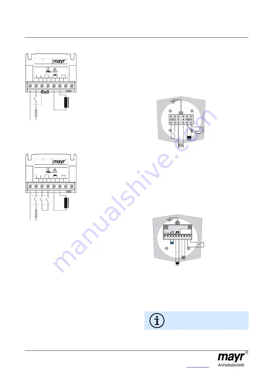
Example of an electrical connection
With terminal block
With microswitch for release monitoring
With anti-condensation heating
Terminal assignment:
1/2: Release monitoring
3/4: AC voltage supply (AC voltage)
for anti-condensation heating
5/6: DC voltage supply (DC voltage)
for brake coil
Fig. 10
Example of an electrical connection
With mayr
®
rectifier
With microswitch for release monitoring
With anti-condensation heating
Terminal assignment:
1/2: AC voltage supply (AC voltage)
for brake coil
7/8: AC voltage supply (AC voltage)
for anti-condensation heating
9/10: Release monitoring
Fig. 11
For short engagement times, a switching
contact at "S
1
" is necessary, which means
DC-side switching.
F1: External fuse
Coil
S1
F1
L
N
1
2
3
4
5
6
7
8
1 2 3 4 5 6 7 8
20/017.000.2
200 - 500V~
200 - 300V~
:
R
IN
OUT
U– = 0,45×U~
+
–
S
DC
ROBA -switch
I
= 1,8A
max
–
0,05-2sec
0 -10M
Ω
Ω
t:
R
R
F1: External fuse
Coil
S1
F1
L
N
1
2
3
4
5
6
7
8
1 2 3 4 5 6 7 8
20/017.000.2
200 - 500V~
200 - 300V~
:
R
IN
OUT
U– = 0,45×U~
+
–
S
DC
ROBA -switch
I
= 1,8A
max
–
0,05-2sec
0 -10M
Ω
Ω
t:
R
R
Earthing connection
Varistor (customer-side)
Brake coil
Anti-condensation heating (AC)
Release monitoring
microswitch
1 2 3 4 5 6 7 8 9 10
Contacts
potantialfree
Netz
AC
S1
Sp1
1 2 3 4 5 6 7 8 9 10
Contacts
potentialfree
Netz
AC
S1
Sp1
Brake coil
Anti-condensation heating (AC)
Release monitoring
microswitch