background image

Installation Guidelines 

Note: Installation should be performed by a trained Service Technician. 
For proper operation of the ice machine, the following installation guidelines must be followed. 
Failure to do so may result in loss of production capacity, premature part failures, and may void all 
warranties. 
 

Ambient Operating Temperatures 

Minimum Operating Temperature: 50°F (10°C) 
Maximum Operating Temperature 100°F (38°C). 

Note: These products are not designed for outdoor installation. 
 
Incoming Water Supply 

Minimum incoming water temperature: 40°F (5°C) 
Maximum incoming water temperature: 90°F (32°C) 
Minimum incoming water pressure: 15 psig 
Maximum incoming water pressure: 80 psig 

Note: If water pressure exceeds 80 psig, a water pressure regulator must be installed. 
 
Drains: 

Route bin drain, purge drain and water condenser drain individually to a floor drain. The 

use of condensate pumps for draining water on equipment producing over 200 lbs./day is not 
recommended by Manufactor. We assumes no responsibility for improperly installed equipment. 
 

Water Filtration 

A water filter system should be installed with the ice machine. 
 

Clearance Requirements 

Self contained air cooled ice machines must have a minimum of 6 inches (15cm) of clearance at the 
rear, top, and sides of the ice machine for proper air circulation. Since undercounter machines 
breathe from the front, top and side clearances are minimal. 
 

Stacking 

If the ice machines are to be stacked, refer to the instructions in the stacking kit. We does not 
endorse stacking aircooled ice machines. 
 

Dispenser Application 

A thermostatic bin control kit must be installed if the ice machine is placed on a dispenser. A bin 
top may or may not be required. 
 

Ice Maker Maintenance 


Maintenance Procedure 

1. Clean the icemaking section per the instructions below. Cleaning should be performed a 
minimum of every 6 months. Local water conditions may require that cleaning be performed more 
often. 
2. Check ice bridge thickness. Proper thickness should be 1/16-1/8’’. 
3. Check water level in trough. See troubleshooting for proper water level and adjustment. 
4. Clean the condenser to insure unobstructed air flow. 
5. Check for leaks of any kind: Water, Refrigerant, Oil, Etc. 
6. Check the bin switch for proper adjustment. 
7. Check all electrical connections. 

Содержание MIM1000

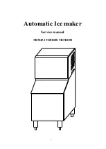
Страница 1: ...1 Automatic Ice maker Service manual MIM452 MIM600 MIM1000...

Страница 2: ...Works 4 Water System 7 Wiring Connections and Controller 9 Exploding Drawing 12 TroubleShooting 14 Before Maintenance 14 Basic Checking 14 TroubleshootingGuide 15 Adjustment and Replacement 20 Advanc...

Страница 3: ...t Water Filtration A water filter system should be installed with the ice machine Clearance Requirements Self contained air cooled ice machines must have a minimum of 6 inches 15cm of clearance at the...

Страница 4: ...oth to remove any remaining residue If necessary remove the water distribution tube disassemble and clean with a bottlebrush Reassemble all components and repeat steps 4 through 7 as required to remov...

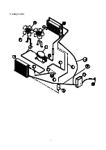
Страница 5: ...5 Cooling System...

Страница 6: ...ol the liquid refrigerant after passing through the condenser The drier and filter reduce possible dirt and moisture in the refrigerant The refrigerant expands in the evaporator cooling it so ice will...

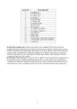
Страница 7: ...et tube 7 Floater valve 8 Water trough 9 Water pump 10 Water pump outlet tube 11 Water distribution tube 12 Evaporator Ice Mold 13 Ice full sensor 14 Drain pipe connector 15 Drain pipe hex nut 16 Drai...

Страница 8: ...ugh to the water distribution tube The distributed water flows over the surface of the cold evaporator where the purest water is converted to ice The unfrozen water returning to the trough At the end...

Страница 9: ...9 Wiring Connection...

Страница 10: ...rks regularly to keep the lower temperature for lower ice melting The rest of the electric components are powered off The WHITE LED indicates the ice full status and the GREEN AND YELLOW LEDs together...

Страница 11: ...e in the Ice Size Adjustment mode press the Clean button or the Mode button for the desired ice size Smaller ice setting By pressing the Clean button you can decrease the size of the ice cubes The FUL...

Страница 12: ...12 Exploding Drawing...

Страница 13: ...pipe 17 Water outlet pipe screw 18 water outlet pipe screw 19 Water inlet connector 20 foaming PE 21 top panel 22 compressor starting device component 23 compressor 24 discharge pipe1 25 suction pipe...

Страница 14: ...ront panel 48 compressor base 49 left panel 50 knob 51 compressor base support 52 Water distributor tube 53 Water out of pump 54 water pump support 55 Water pump 56 Drain pipe 57 Drain pipe connector...

Страница 15: ...he cycle of the icemaking and ice harvesting normal Does water run is the fan running and is the evaporator getting cold enough Check the water system especially at the connections Are there any water...

Страница 16: ...16...

Страница 17: ...17...

Страница 18: ...18...

Страница 19: ...19...

Страница 20: ...20...

Страница 21: ...e steps to reassemble Replacing the cooling system components To replace the condensing components see the Cooling System figure 1 Replacing the compressor and the compressor kit includes relay therma...

Страница 22: ...condenser The refrigerant changes to a liquid when cooled The refrigerant in a liquid state passes through a filter drier The filter drier traps small amounts of moisture and foreign particles from t...

Страница 23: ...proper voltage is supplied to the compressor and all wiring is properly connected If the compressor does not start and there is excessive amperage draw see locked rotor amps on compressor tag the com...

Страница 24: ...l suction pressure A low refrigerant charge will also starve the evaporator and cause low suction and discharge pressures If not sure of the amount of charge in the system the refrigerant should be re...

Страница 25: ...until the timer has energized Check the evaporator for areas where cubes are less developed than cubes in other areas If the cubes are all the same size coil separation is not the problem If there ar...

Страница 26: ...cycle When the freeze timer is energized the machine is in the timed portion of the freeze cycle When the machine enters harvest the temperature rises but the amount of time the machine is in harvest...

Страница 27: ...switch which detects its position When ice is sitting on the control the slideway faces down indicating that ice is present and disconnecting the circuit from the reed switch When the ice is removed t...

Страница 28: ...re sensor of condenser 19 3 1851700501 Temperature sensor of evaporator 20 1858442400 Transformer 24 1854700800 Drain valve 28 1854601900 Expansive valve 29 1 1854704410 Hot gas valve body 29 2 185470...

Отзывы: