21
Adjustment and Replacement
Replace Control box, fuse and the sensor of temperature
Replacing Control Box Fuse and Temperature Sensor
Remove the rear cover and the louvered front panel or the side panel on a modular unit.
Locate the electronic control box in the unit.
Carefully pull out the temperature sensors (one at the evaporator, another at the condenser).
Loosen the screws holding the control box, replace with a new one. Reverse the foregoing steps
to reassemble.
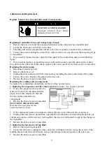
If you need to replace the fuse, open the front panel of the control box and you will find this
figure:
If you need to replace a temperature sensor, pull out the sensor, open the panel of the control
box, pull out the other end of the sensor, replace with a new one. Reverse these steps to reassemble.
Replacing the water pump
Disconnect electrical power.
Remove the front cover.
Unplug the lines connected with the water pump, including the water outlet tube of the pump.
Loosen the screws. Replace the pump with a new one.
Reverse the above steps to reassemble.
Replacing the cooling system components
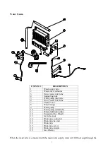
To replace the condensing components, see the
Cooling System
figure.
1. Replacing the compressor and the compressor kit
(includes relay, thermal protect)
If only the compressor kit needs to be
replaced, remove the top panel and left
panel, locate the compressor, take off
the clip, replace the defective
components.
Reverse the above steps to reassemble.
ELECTRICAL SHOCK HAZARD
Disconnect electrical power before
beginning removal of parts.
If the compressor needs to be replaced, remove the top cover and locate the compressor.
Unplug lines and remove ground line, open the Process/Suction, evacuate refrigerant, take out
compressor, replace with a new one, join together, then recover refrigerant, weigh in the charge on
the nameplate.
Reverse the above steps to reassemble.
2. Replacing the fan motor and fan blade
Remove the top and right panels.
Locate the fan motor, unplug the lines connected with the fan motor, loosen the screws of the
holding bracket and fan motor bracket, remove the damaged unit and replace with a new one.
Reverse the above steps to reassemble.
ELECTRICAL SHOCK HAZARD
Disconnect Electrical Power Before
Beginning Removal of Parts
Содержание MIM1000
Страница 1: ...1 Automatic Ice maker Service manual MIM452 MIM600 MIM1000...
Страница 5: ...5 Cooling System...
Страница 9: ...9 Wiring Connection...
Страница 12: ...12 Exploding Drawing...
Страница 16: ...16...
Страница 17: ...17...
Страница 18: ...18...
Страница 19: ...19...
Страница 20: ...20...

