background image

Visit: www.seekerwireless.co.uk for potential software updates

Page 13


Pairing Control Panel and Control Box:

Every Control Panel made by Maxview contains a unique electronic identification number to prevent 
interference between neighbouring Seeker satellite systems. When the Control Panel and Control Box are not 
paired the Control Panel displays RF ERROR.

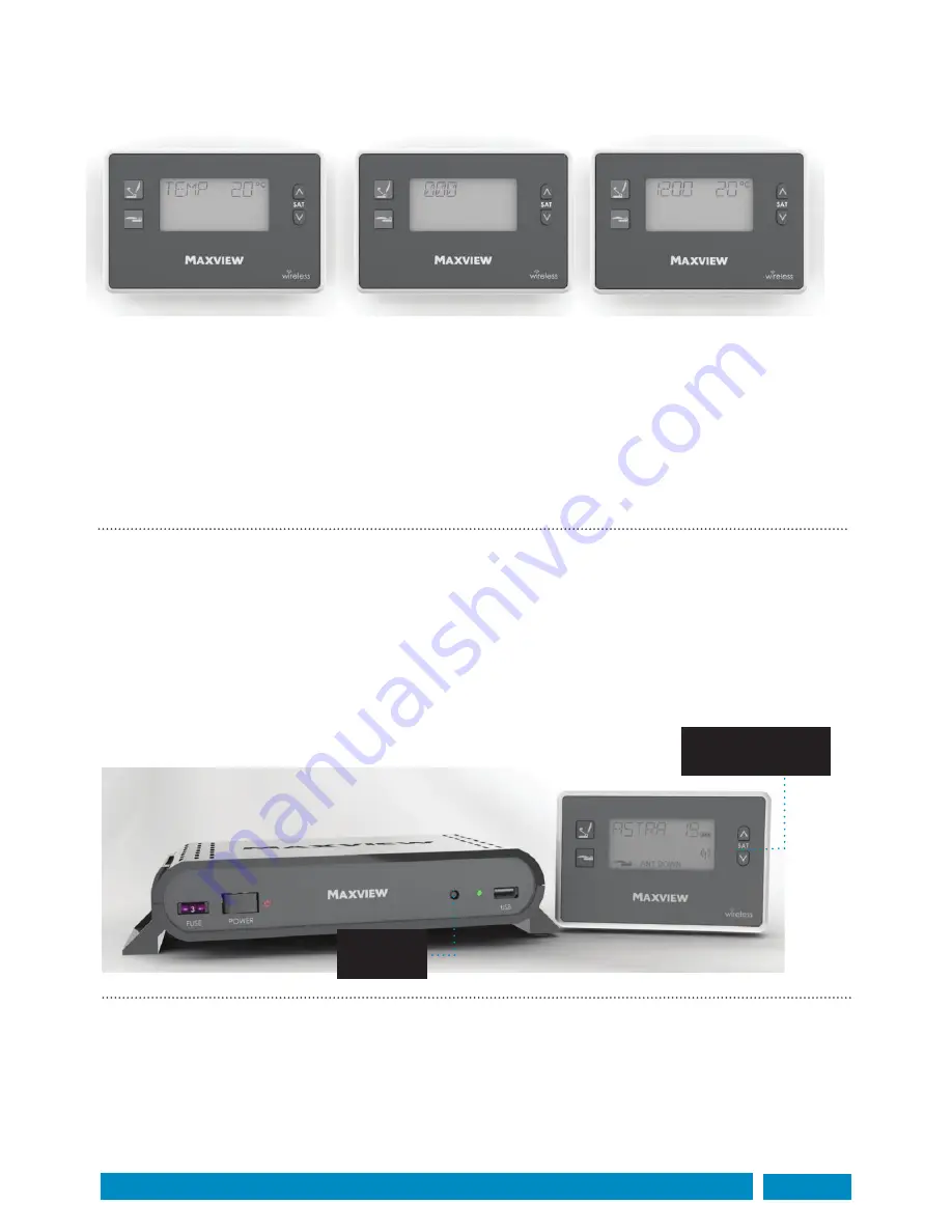
To pair the Control Box and Panel together press and release the Sync Button on the front of the Control Box. 
The Status LED will illuminate green. Then press Satellite UP or Down button on the panel to synchronise.

This operation is only required during installation and after any software updates.

Cable mode:

The Control Panel and Box can also be connected through the included RJ25 cable. 
In this mode no batteries are required.

Note: 

If a different cable to the one supplied is to be used ensure that it is an RJ25 6 Pin 6 Connector cable. 

RJ11 and RJ14 cables use the same connector but contain 2 and 4 wires respectively and will not function with 
the Control Panel.

Time and temperature display:

The Control Panel will automatically display the ambient temperature when the antenna is not in use. 

To enable the clock function: 

1. 

Press and hold Satellite UP and Down buttons for 3 seconds

2. 

The clock will be shown with the Hour digits flashing. Press Up or Down buttons to adjust the hours. 

3. 

Press the Satellite Search button to select the minutes. Press Up or Down buttons to adjust minutes.

4. 

Press Antenna Park button to Exit.

The clock will be displayed when the panel has been inactive for 10 seconds.

Note:

 The clock requires power from the batteries. Turning the panel off via the switch or changing the 

batteries will disable the clock function. The clock is 24 hour display only.

Press Satellite UP/
DOWN Button

Press Sync
Button

Содержание MXL003/65

Страница 1: ...ing instructions MXL003 65 85 Seeker Wireless UK contact Helpline 44 0 1553 811000 Email support maxview co uk Web www maxview co uk Maxview reserve the right to change specifications without prior no...

Страница 2: ...nstruction of the roof structure should be suitably robust and have no protruding obstacles 2 The Control Box is designed to be mounted internally in a cupboard it controls the antenna unit through a...

Страница 3: ...n The Control Box and Control Panel are for internal use only and are not waterproof Operation Before starting your journey check that antenna is in the park position The maximum speed of vehicle with...

Страница 4: ...the Twin LNB B Control Box The Control Box requires wired connections for power antenna control and satellite signal It can be mounted discretely in a cupboard and can be fixed vertically and horizont...

Страница 5: ...nna Unit Control Box Control Panel 65 85cm Antenna separate carton Accessory Pack LNB Park Plate x 1 Control Box bracket x 2 Control Panel mount x 1 RJ25 Cable x 1 Battery 1 5v AA x 2 Power Cable x 1...

Страница 6: ...3 F 43 E A D B C H G F I G 52 H 15 I 110 G 64 H 14 I 125 Mounting plate Positioning Control Box Site the Control Box in a convenient location where Front and rear connections are accessible Cables can...

Страница 7: ...he roof Note Follow manufacturer s instructions when applying adhesive Do not travel until adhesive has cured noting that curing times vary with weather conditions Take care when working at heights Al...

Страница 8: ...ce such as electric igniters for gas stoves Route cables carefully avoiding areas of excessive heat such exhaust systems and any moving parts in the engine compartment or drive shafts Power Cable colo...

Страница 9: ...dly assembled and disassembled Installing cables 1 Check there are no hidden cables in the roof structure and that the hole location is clear of obstructions both internally and externally 2 Turn over...

Страница 10: ...n 1 Clip the mounting brackets onto the Control Box 2 Place Control Box on the horizontal or vertical surface and mark the 4 holes 3 Depending on material drill a pilot hole or use a bradawl 4 Attach...

Страница 11: ...ach to wall with 2 No 6 screws Cable mode 1 Choose a location to mount the Control Panel 2 Mark the fixing holes then make a pilot hole with a drill or bradawl 3 If required remove one of the knock ou...

Страница 12: ...reverse of Control Box to elevate antenna Once elevated turn off power to Control Box and remove fuse 3 Fix satellite dish to Antenna Arm using M6 Button Head Screws M6 Nuts and 6mm Plastic Washers Th...

Страница 13: ...a different cable to the one supplied is to be used ensure that it is an RJ25 6 Pin 6 Connector cable RJ11 and RJ14 cables use the same connector but contain 2 and 4 wires respectively and will not fu...

Страница 14: ...han 1 minute The first search from the factory set position may take as much as 15 minutes If the Seeker cannot find the desired satellite it will automatically return to the Park position and display...

Страница 15: ...Box the power must be on Power consumption The Seeker Wireless has been designed to minimise power consumption When not in use the system enters a sleep mode where wireless communication between the C...

Страница 16: ...Skew adjustment is required when signal strength is weak at the limit of a given satellites reception area It involves adjusting the angle of the LNB on the roof mounted antenna unit Caution Follow g...

Страница 17: ...d copy onto a formatted USB flash memory stick 2 Turn on Control Box 3 Press and hold the SYNC button on the front of the Control Box for 7 seconds until SYNC LED illuminates RED 4 Insert the USB flas...

Страница 18: ...vehicle ignition before operating antenna Battery power has been interrupted Reset clock see page 12 Batteries exhausted Replace batteries or use cable connection Check Control Panel power switch is o...

Страница 19: ...any indirect incidental or consequential damages from the sale or use of the product This disclaimer applies both during and after the term of the guarantee This does not affect your statutory rights...

Страница 20: ...NB Type High Quality 0 2dB Universal Twin LNB Output Twin Typical Gain 65cm 36dB 85cm 38 1dB Frequency Range 10 7 12 75GHz Arm Cable RG179 Antenna Material Aluminium Reflector Thickness 1mm Finish Pow...

Отзывы: