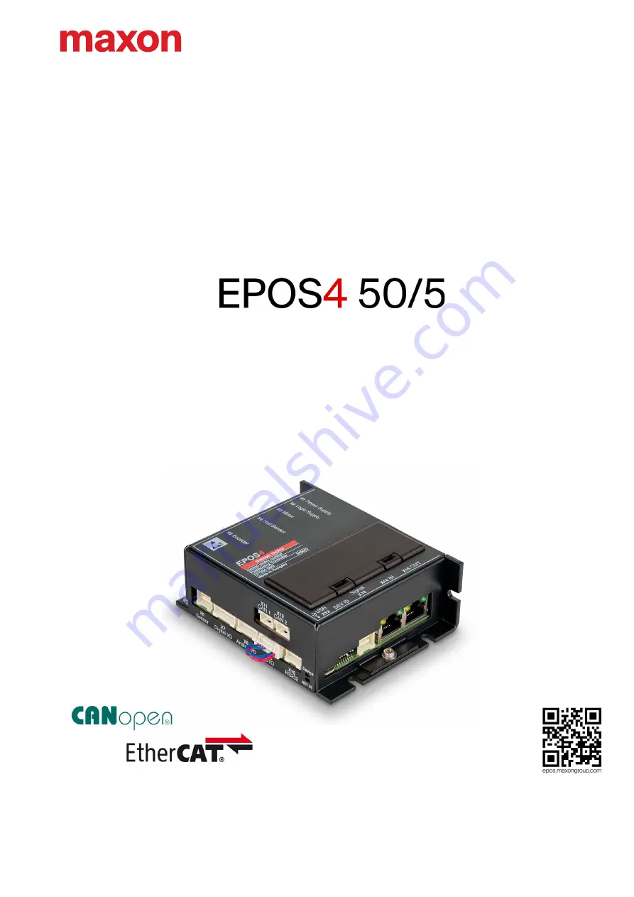
EPOS4 50/5 Positioning Controller | P/N 546047
Hardware Reference
CCMC | Edition 2022-04 | DocID rel10445
Страница 1: ...EPOS4 50 5 Positioning Controller P N 546047 Hardware Reference CCMC Edition 2022 04 DocID rel10445 Hardware Reference...
Страница 2: ...AD THIS FIRST These instructions are intended for qualified technical personnel Prior commencing with any activities you must carefully read and understand this manual and you must follow the instruct...
Страница 3: ...52 3 3 14 Extension Signal X16 53 3 3 15 Extension Slots EXT1 EXT2 54 3 3 16 DIP Switch Configuration SW1 56 3 3 16 1 CAN ID Node ID DEV ID 56 3 3 16 2 CAN automatic Bit Rate Detection 57 3 3 16 3 CAN...
Страница 4: ...Table of Contents EPOS4 50 5 Hardware Reference A 4 CCMC 2022 04 rel10445 p a g e i n te n ti o n a l l y l e ft b l a n k...
Страница 5: ...ous situations to keep installation and or commissioning time at a minimum to increase reliability and service life of the described equipment The present document is part of a documentation set and c...
Страница 6: ...result in death or serious injury WARNING Indicates a potential hazardous situation If not avoided it can result in death or serious injury CAUTION Indicates a probable hazardous situation or calls t...
Страница 7: ...val is not permitted The men tioned trademarks belong to their respective owners and are protected under intellectual property rights 2022 maxon All rights reserved Subject to change without prior not...
Страница 8: ...Safety Precautions Keep in mind Safety first Always Make sure that you have read and understood the note READ THIS FIRST on page A 2 Do not engage with any work unless you possess the stated skills ch...
Страница 9: ...d EC motor block 100 000 rpm 1 pole pair Max speed EC motor sinusoidal 50 000 rpm 1 pole pair Built in motor choke 3 x 15 H 5 A Inputs Outputs Digital Input 1 general purpose Digital Input 2 general p...
Страница 10: ...s to IEEE 802 3 100 Base T Status Indicators Device Status Operation green LED Error red LED NET Status RUN state green LED Error red LED NET Port Link activity green LED Physical Weight approx 206 g...
Страница 11: ...Specifications Thermal Data EPOS4 50 5 Hardware Reference CCMC 2022 04 rel10445 2 11 2 2 Thermal Data 2 2 1 Derating of Output Current Figure 2 2 Derating of output current...
Страница 12: ...45 2 2 2 Power Dissipation and Efficiency Figure 2 3 Power dissipation and efficiency 2 3 Limitations Table 2 5 Limitations Protection functionality Switch off threshold Recovery threshold Undervoltag...
Страница 13: ...Specifications Dimensional Drawing EPOS4 50 5 Hardware Reference CCMC 2022 04 rel10445 2 13 2 4 Dimensional Drawing Figure 2 4 Dimensional drawing mm...
Страница 14: ...eric IEC EN 61000 6 2 Immunity for industrial environments IEC EN 61000 6 3 Emission standard for residential commercial and light industrial environments Applied IEC EN 55022 CISPR22 Radio disturbanc...
Страница 15: ...g hot plugged connecting while the power supply is on the possibly high poten tial differences of the two power supplies of controller and PC Notebook can lead to damaged hardware Avoid potential diff...
Страница 16: ...Cable Assembly Designation Part Number Page X1 Power Cable Mandatory for supply of power stage 275829 3 19 X2 Power Cable Optional for separate logic supply 275829 3 19 X3 Motor Cable 275851 3 22 X4 H...
Страница 17: ...X6 X16 Molex CLIK Mate dual row 10 poles 503149 1000 1 X7 X9 Molex CLIK Mate single row 8 poles 502578 0800 2 X8 Molex CLIK Mate single row 7 poles 502578 0700 1 X10 Molex CLIK Mate single row 5 poles...
Страница 18: ...he first column describes both the pin number of the connector and of the matching prefab maxon cable s Head A The second column describes the cable core color of the prefab maxon cable The third colu...
Страница 19: ...ply Best practice Keep the motor mechanically disconnected during the setup and adjustment phase Figure 3 6 Power supply connector X1 Table 3 10 Power supply connector X1 Pin assignment Table 3 11 Pow...
Страница 20: ...sure that the overcurrent pro tection circuit is configured inoperative within the operating range The formula already takes the following into account Maximum PWM duty cycle of 90 Controller s max v...
Страница 21: ...logic supply is internally connected to the power supply Figure 3 7 Logic supply connector X2 Table 3 13 Logic supply connector X2 Pin assignment For the matching prefab cable assembly Table 3 11 Tab...
Страница 22: ...b Cable Head B Signal Description Pin Color Pin 1 white Motor M DC motor Motor 2 brown Motor M DC motor Motor 3 green not connected 4 black Motor shield Cable shield X3 Head A Prefab Cable Head B Sign...
Страница 23: ...Head A Prefab Cable Head B Signal Description Pin Color Pin 1 green Hall sensor 1 Hall sensor 1 input 2 brown Hall sensor 2 Hall sensor 2 input 3 white Hall sensor 3 Hall sensor 3 input 4 yellow GND G...
Страница 24: ...ure 3 10 Hall sensor 1 input circuit analogously valid for Hall sensors 2 3 Hall sensor Sensor supply voltage VSensor 5 VDC Max Hall sensor supply current 30 mA Input voltage 0 24 VDC Max input voltag...
Страница 25: ...r X5 Table 3 21 Encoder connector X5 Pin assignment Table 3 22 Encoder connector X5 Accessories Continued on next page X5 Head A Prefab Cable Head B Signal Description Pin Color Pin 1 brown 1 not conn...
Страница 26: ...e Encoder Cable 275934 Cross section 10 x AWG28 round jacket flat cable pitch 1 27 mm Length 3 m Head A DIN 41651 female pitch 2 54 mm 10 poles with strain relief Head B DIN 41651 plug pitch 2 54 mm 1...
Страница 27: ...d for Ch B Ch I Encoder single ended Sensor supply voltage VSensor 5 VDC Max encoder supply current 70 mA Input voltage 0 5 VDC Max input voltage 12 VDC Logic 0 1 0 V Logic 1 2 4 V Input high current...
Страница 28: ...tal analog incremental encoder channel A complement HsDigIN1 High speed digital input 1 complement 3 green 3 Channel B Digital analog incremental encoder channel B HsDigIN2 High speed digital input 2...
Страница 29: ...B Continued on next page Sensor Cable 5x2core 520852 Cross section 5 x 2 x 0 14 mm2 twisted pair grey Length 3 m Head A Plug Molex CLIK Mate dual row 10 poles 503149 1000 Contacts Molex CLIK Mate crim...
Страница 30: ...Setup Connections EPOS4 50 5 Hardware Reference 3 30 CCMC 2022 04 rel10445 Figure 3 16 Digital incremental encoder input circuit Ch I Continued on next page...
Страница 31: ...xt page Digital incremental encoder single ended Auxiliary output voltage VAux 5 VDC Max auxiliary supply current 150 mA Input voltage 0 5 VDC Max input voltage 12 VDC Logic 0 1 0 V Logic 1 2 4 V Inpu...
Страница 32: ...Setup Connections EPOS4 50 5 Hardware Reference 3 32 CCMC 2022 04 rel10445 Figure 3 18 Digital incremental encoder input circuit Ch I Continued on next page...
Страница 33: ...ircuit Ch A differential analogously valid for Ch B Continued on next page Analog incremental encoder SinCos differential Auxiliary output voltage VAux 5 VDC Max auxiliary supply current 150 mA Input...
Страница 34: ...Setup Connections EPOS4 50 5 Hardware Reference 3 34 CCMC 2022 04 rel10445 Figure 3 20 Analog incremental encoder input circuit Ch I digital evaluation Continued on next page...
Страница 35: ...solute encoder data input Figure 3 22 SSI absolute encoder clock output SSI absolute encoder Auxiliary output voltage VAux 5 VDC Max auxiliary supply current 150 mA Min differential input voltage 200...
Страница 36: ...peed digital I O operation Table 3 32 Differential high speed digital input specification Figure 3 23 HsDigIN1 circuit differential analogously valid for HsDigIN2 4 Continued on next page High speed d...
Страница 37: ...ended analogously valid for HsDigIN2 4 Continued on next page High speed digital input 1 4 single ended Input voltage 0 5 VDC Max input voltage 12 VDC Logic 0 1 0 V Logic 1 2 4 V Input high current t...
Страница 38: ...Table 3 34 High speed digital output specification Figure 3 25 HsDigOUT1 output circuit High speed digital output 1 Min differential output voltage 1 8 V external load R 54 Max output current 40 mA L...
Страница 39: ...lor Pin 1 white 1 DigIN1 Digital input 1 2 brown 2 DigIN2 Digital input 2 3 green 3 DigIN3 Digital input 3 4 yellow 4 DigIN4 Digital input 4 5 grey 5 DigOUT1 Digital output 1 6 pink 6 DigOUT2 Digital...
Страница 40: ...e 3 28 DigIN1 circuit analogously valid for DigIN2 4 PLC level setting Continued on next page Digital inputs 1 4 Logic level setting Input voltage 0 30 VDC Max input voltage 30 VDC Logic 0 0 8 V Logic...
Страница 41: ...ence CCMC 2022 04 rel10445 3 41 Table 3 39 Digital output specification Figure 3 29 DigOUT1 circuit analogously valid for DigOUT2 Continued on next page Digital outputs 1 2 Circuit Open drain internal...
Страница 42: ...nks analogously valid for DigOUT2 Table 3 41 Digital output Source Figure 3 31 DigOUT1 source analogously valid for DigOUT2 DigOUT sinks Max input voltage 36 VDC Max load current 500 mA Max voltage dr...
Страница 43: ...lor Pin 1 white 1 AnIN1 Analog input 1 positive signal 2 brown 2 AnIN1 Analog input 1 negative signal 3 green 3 AnIN2 Analog input 2 positive signal 4 yellow 4 AnIN2 Analog input 2 negative signal 5 g...
Страница 44: ...VDC differential Max input voltage 24 VDC Common mode voltage 5 10 VDC referenced to GND Input resistance 80 k differential 65 k referenced to GND A D converter 12 bit Resolution 5 64 mV Bandwidth 10...
Страница 45: ...ble 3 47 must be plugged Table 3 46 STO connector X9 Pin assignment For the matching prefab cable assembly Table 3 36 on page 3 39 Table 3 47 STO Idle Connector Continued on next page X9 Head A Prefab...
Страница 46: ...age Safe Torque Off inputs 1 2 Circuit type Optically isolated input Input voltage 0 30 VDC Max input voltage 30 VDC Logic 0 1 0 VDC Logic 1 4 5 VDC Input current at logic 1 2 mA 5 VDC typically 3 2 m...
Страница 47: ...ns EPOS4 50 5 Hardware Reference CCMC 2022 04 rel10445 3 47 Table 3 50 STO logic state STO Logic State STO IN1 STO IN2 STO OUT Power Stage 0 0 open inactive 1 0 closed inactive 0 1 closed inactive 1 1...
Страница 48: ...eceive 2 brown 5 GND Ground 3 green 2 EPOS_TxD EPOS RS232 transmit 4 yellow 5 GND Ground 5 Shield Housing Shield Cable shield RS232 COM Cable 520856 Cross section 2 x 2 x 0 14 mm2 twisted pair shielde...
Страница 49: ...connector X11 CAN 2 connector X12 Table 3 54 CAN 1 connector X11 CAN 2 connector X12 Pin assignment Table 3 55 CAN COM Cable Continued on next page X11 X12 Head A Prefab Cable 520857 Head B 520858 Hea...
Страница 50: ...information see separate document EPOS4 Communication Guide CAN CAN Cable 520858 Cross section 2 x 2 x 0 14 mm2 twisted pair shielded Length 3 m Head A Plug Molex CLIK Mate single row 4 poles 502578 0...
Страница 51: ...then switch on the power supply of the controller Figure 3 40 USB connector X13 Table 3 58 USB connector X13 Pin assignment Table 3 59 USB Type A micro B Cable Table 3 60 USB interface specification...
Страница 52: ...connect them as follows Use only standard Cat5 cables with RJ45 plug such as maxon s Ethernet Cable 422827 Use IN X14 as Input Use OUT X15 as Output For detailed information see separate document EPO...
Страница 53: ...tension card Figure 3 42 Extension Signal connector X16 Table 3 63 Extension Signal connector X16 Pin assignment For the matching prefab cable assembly Table 3 27 on page 3 29 Ethernet Cable 422827 Cr...
Страница 54: ...ve network For further details see separate document EPOS4 Communication Guide EXT2 provides connectivity for advanced signal extension cards such as for additional absolute sensors or customized sign...
Страница 55: ...ts corners 4 Insert the catch into the extension card s bore C 5 Pull both the plastic lid together with the extension card straight upward D Make sure that the extension slots are clean and free of a...
Страница 56: ...f DIP switches 1 5 The ID 1 31 may be coded using binary code Setting the ID by DIP switch SW1 By setting the DIP switch 1 5 address 0 OFF the ID may be set by software object 0x2000 Node ID range 1 1...
Страница 57: ...Table 3 67 DIP switch SW1 CAN automatic bit rate detection 3 3 16 3 CAN Bus Termination Table 3 68 DIP switch SW1 CAN bus termination Setting Switch ID 1 2 3 4 5 0 0 0 0 0 1 0 0 0 0 1 0 1 0 0 0 2 0 0...
Страница 58: ...16 4 Digital Input Level For details chapter 3 3 7 Digital I O X7 on page 3 39 Table 3 69 DIP switch SW1 Digital input level 3 3 17 Spare Parts Table 3 70 Spare parts list Switch OFF ON 8 Logic level...
Страница 59: ...Green LED shows the RUN state Red LED indicates errors Table 3 71 NET Status LEDs LED Description Green Red OFF EPOS4 is in state INIT Blink EPOS4 is in state PRE OPERATIONAL Single flash EPOS4 is in...
Страница 60: ...Port LED LED Description Green Red Slow OFF Power stage is disabled The EPOS4 is in status Switch ON Disabled Ready to Switch ON Switched ON ON OFF Power stage is enabled The EPOS4 is in status Operat...
Страница 61: ...nnectivity and pin assignment Or you may wish to use the connection overviews for either DC motor or EC BLDC motor that will assist you in determining the wiring for your particular motor type and the...
Страница 62: ...e corresponding wiring method and follow the link or links to the stated figure s to find the relevant wiring information 4 1 1 DC Motor Power supply optional logic supply Figure 4 49 Motor feedback s...
Страница 63: ...incremental encoder Analog incremental encoder SinCos Method EC7 Hall sensors Digital encoder SSI absolute encoder Method EC8 Digital incremental encoder SSI absolute encoder Method EC9 SSI absolute e...
Страница 64: ...Wiring Main Wiring Diagram EPOS4 50 5 Hardware Reference 4 64 CCMC 2022 04 rel10445 4 2 Main Wiring Diagram Figure 4 48 Main wiring diagram Figure 4 54 Figure 4 55 Figure 4 56...
Страница 65: ...ce CCMC 2022 04 rel10445 4 65 4 3 Excerpts 4 3 1 Power Logic Supply Figure 4 49 Power logic supply 4 3 2 DC Motor Figure 4 50 DC motor 4 3 3 EC BLDC Motor Figure 4 51 EC BLDC motor 4 3 4 Hall Sensors...
Страница 66: ...gital Incremental Encoder 1 Sensor 1 Figure 4 53 Digital incremental encoder 1 Sensor 1 4 3 6 Digital Incremental Encoder 2 Sensor 2 Figure 4 54 Digital incremental encoder 2 Sensor 2 4 3 7 Analog inc...
Страница 67: ...Wiring Excerpts EPOS4 50 5 Hardware Reference CCMC 2022 04 rel10445 4 67 4 3 8 SSI Encoder Sensor 2 Figure 4 56 SSI encoder Sensor 2...
Страница 68: ...Wiring Excerpts EPOS4 50 5 Hardware Reference 4 68 CCMC 2022 04 rel10445 p a g e i n te n ti o n a l l y l e ft b l a n k...
Страница 69: ...tal encoder input circuit Ch A differential analogously valid for Ch B 33 Figure 3 20 Analog incremental encoder input circuit Ch I digital evaluation 34 Figure 3 21 SSI absolute encoder data input 35...
Страница 70: ...Figure 3 46 LEDs Location 59 Figure 4 47 Interfaces Designations and location 61 Figure 4 48 Main wiring diagram 64 Figure 4 49 Power logic supply 65 Figure 4 50 DC motor 65 Figure 4 51 EC BLDC motor...
Страница 71: ...der connector X5 Pin assignment 25 Table 3 22 Encoder connector X5 Accessories 25 Table 3 23 Encoder Cable 26 Table 3 24 Differential encoder specification 26 Table 3 25 Single ended encoder specifica...
Страница 72: ...Table 3 57 CAN interface specification 50 Table 3 58 USB connector X13 Pin assignment 51 Table 3 59 USB Type A micro B Cable 51 Table 3 60 USB interface specification 51 Table 3 61 Extension IN OUT c...
Страница 73: ...3 country specific regulations 8 D DEV ID see ID device condition display of 59 digital high speed inputs differential 36 digital high speed inputs single ended 37 digital high speed output 38 digital...
Страница 74: ...supply requirements 21 precautions 8 prerequisites prior installation 15 prohibitive signs 6 protective measures ESD 8 54 purpose of the device 8 of the document 5 R regulations applicable 8 Requirem...
Страница 75: ...EPOS4 50 5 Hardware Reference CCMC 2022 04 rel10445 Z 75 Index p age intention ally left blank...
Страница 76: ...means of electronic data processing without prior written approval is not permitted The mentioned trademarks belong to their respective owners and are protected under intellectual property rights 202...