S110908 Mentor-G V2
15.
Insert the aileron’s CA hinges in their precut slots and test fit each aileron to its wing panel.
Secure the
ailerons
to their wing panels by applying thin CA adhesive to each of the aileron’s CA hinges.
16.
Test-fit the
aileron control horns
. (Note: You may minimize the effects of any possible
adverse yaw
by
the use of ‘aileron differential’ by locating each servo horn’s opening
behind
the aileron’s hinge line. If you
are not concerned about adverse yaw, or if you have a computer-radio with the option of setting up aileron
differential at your transmitter, position each aileron control horn opening over each aileron’s hinge line.)
Mark the position for each aileron control horn, drill a hole in each aileron
for each aileron control horn’s mounting bolt, and attach one control horn
to each aileron. Using your servos’ hardware, mount your aileron servos in
their precut openings.
17.
Using the pre-formed Z-bends and the supplied clevises, attach the 4-inch
long
aileron pushrods
.
18.
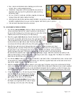
Once all the clevises are adjusted, permanently secure each push-rod
within its clevis with a few drops CA.
Note:
a) It is difficult to form new Z-bends in the supplied heavy-gauge
pushrods; so, if you
need to ‘shorten’ a
push-rod, you may
simply form an
extended, shallow Z-
bend near the middle
of the rod, as shown.
b) If you wish to enjoy the
benefits of flying with flaps, use separate channels for the ailerons and set up your computer-radio’s
‘flaperon’
function (if available).
19.
Form a Z-bend in one end of the 13-inch long
throttle pushrod
. Insert the pushrod almost fully through its
opening in the firewall, leaving approx. two or three inches exposed in front of the firewall.
20.
Select a servo control arm for your throttle servo that will provide enough pushrod ‘travel’ to go from ‘full
throttle’ to ‘just-below idle’ (i.e., throttle ‘cut-off’). Ream the hole in the throttle servo’s control arm to
accept the ‘mounting bolt’ in the end of the supplied quick-connector. Using the provided washers and
knurled mounting nut, ‘snugly’ attach the quick connector to the servo control arm, then permanently affix
the quick connector onto the servo control arm by applying a tiny drop of thick CA adhesive to the exposed
threads at the bottom of the quick connector’s mounting nut.
21.
Slide the opening in the quick-connector onto the end of the throttle pushrod inside the fuselage; temporarily
tighten the quick-connector’s set screw to affix the quick-connector onto the throttle pushrod.
22.
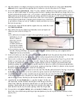
As shown at the right, you may extend the precut opening for the servo lead in either end
of the wooden throttle servo mount by 3/4-inch to allow your throttle servo
and its lead to fit down into the provided wooden throttle servo mount.
23.
Assemble the provided
fuel tank
(i.e., open the ‘stopper’ for the vent
and clunk lines, add the included short length of fuel tubing to attach the
clunk to the clunk line, and use the included screw to seal the fuel tank’s
opening). Attach clunk and vent fuel lines to the outside of the tank, and
insert the tank into the nose from the opening under the wing-saddle.
24.
Test-position your
engine’s battery
and your
receiver’s battery
on the
floor in the nose of the fuselage.(During setup and adjustment you will re-position these batteries to fine-
tune the CG.)
Page 6 of 10


