S110908 Mentor-G V2
25.
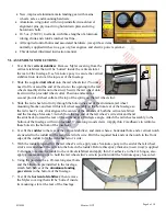
Decide on where you wish to position the engine’s and
receiver’s
power switches
. You may choose from
among the precut switch openings, or decide on a new
switch position if you wish. (Note: Regardless of your
engine’s manufacturer, it is always wise to maximize the
distance between all of your engine’s and radio’s
electrical components.) Trial fit both switches (trim the
openings if necessary) and install the engine and receiver
switches.
26.
Test-fit the engine’s
ignition module
immediately behind the firewall. Decide how
you plan to route the power, sensor and spark-plug wires. (Note: If you find the
ignition module’s spark plug cap does not easily pass through the hole in the fire-
wall, relieve the inside top of the hole in the firewall with a drum sander on a high-
speed rotary tool.)
27.
Test fit your engine (with its muffler) to the firewall. Use the engine’s supplied
standoffs, mounting bolts and blind-nuts to temporarily attach the engine to the
firewall, then determine and mark where
wood needs to be cut away
from the
front of the fuselage to allow clearance for the engine’s cooling fins and muffler.
28.
Remove and set aside the engine.
29.
Remove the excess wood identified above,
and smooth all edges. (We recommend a
drum sander on a high-speed rotary tool.)
Apply 5-minute epoxy to
seal and fuel-proof
all exposed/raw wood.
30.
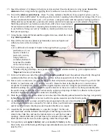
Once the 5-minute epoxy is cured,
install
your engine
and its muffler, and make all
engine connections: As you bring the engine
toward the firewall, your first connection
should be the throttle pushrod’s Z-bend; then,
secure the four sets of mounting bolts and
standoffs (we recommend you apply Lock-
Tite or a similar thread-locking compound).
Route the high-voltage wire along the
engine’s left side, between the cylinder head
and muffler; route the sensor wire and the
fuel and vent lines along the engine’s right-
hand side.
31.
As you
position your throttle servo (
in its
wooden mount) inside the fuselage, place the
throttle servo’s control arm onto your throttle
servo’s output shaft. Attach the servo arm’s
mounting screw, rotate the servo’s shaft to
‘full throttle’ and position the throttle servo
so the engine’s throttle linkage is at ‘full
throttle.’ (If necessary, re-adjust the pushrod
in the throttle arm’s quick connector.)
Page 7 of 10


