


S110908 Mentor-G V2
•
New, improved aluminum main landing gear with mains
wheels, axles, and mounting hardware.
•
Aluminum wing joiner with two preinstalled wood-dowel
alignment pins, plywood wing hold-down plate and wing
hold-down bolts.
•
18.5 oz. (550 CC) fuel tank, with three lengths of aluminum
tubing, clunk and clunk’s internal fuel line.
•
All required control horns and associated hardware (except those items
normally supplied with servos, gas or glow engines, and electric power systems).
•
This detailed, illustrated instruction manual.
VI. ASSEMBLY INSTRUCTIONS:
1.
Test fit the
vertical stabilizer
. Remove Mylar covering from the
vertical stabilizer that will be ‘buried’ inside the vertical slot at
the rear of the fuselage. Use 5-minute epoxy to secure the vertical
stabilizer into its slot at the top-rear of the fuselage.
2.
Slide the supplied
tail wheel
onto the tail wheel strut. (You may
need to file or sand the end of the strut so the opening in the tail
wheel smoothly slides onto the strut.) Secure the tail wheel onto
its strut with a provided wheel collar. Position and secure a
second provided wheel collar at the top of the spring on the tail wheel strut.
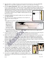
3.
Slide the tail wheel strut fully through the hole in the end of the aluminum tail wheel
mounting bracket, and test fit this tail wheel assembly at the bottom-rear of the fuselage so
the tail wheel’s wire strut aligns at the centers of the aft-ends of both the vertical stabilizer
and the fuselage. Measure 3/4-inch from the top end of the tail wheel’s wire strut and bend
the strut back (toward the rear of the airplane) at a 90-degree angle. Attach the tail wheel assembly to the
bottom of the fuselage with two provided 17-mm long wood screws. (Apply thin CA adhesive to reinforce
these holes in the bottom of the fuselage.)
4.
Test fit the
rudder
to the rear of the vertical stabilizer, and mark where a horizontal hole and a vertical notch
are needed in the rudder for the tail wheel strut’s wire. Drill the required hole and cut the notch in the front
edge of the rudder to fit the tail wheel strut’s wire.
5.
With the rudder prepared for the tail wheel’s wire, apply some 5-minute epoxy to the end of the tail wheel
strut’s wire and insert the wire into the hole in the rudder. Before this epoxy thickens, insert two(2) supplied
CA hinges to secure the rudder to the vertical stabilizer and apply thin CA adhesive to the CA hinges; also
apply some masking tape to hold the tail wheel strut’s wire in position until the 5-minute epoxy has cured.
6.
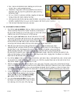
Using the provided 6 ea. 20-mm long steel bolts
and the blind-nuts preinstalled in the fuselage,
attach both halves of the
aluminum landing
gear struts
to the bottom of the fuselage.
7.
Test fit the
horizontal stabilizer
, then remove
the Mylar covering that will be ‘buried’ inside
its mounting- slot at the rear of the fuselage.
Page 4 of 10