Page 7 of 13 pages
31.
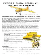
Insert the rudder‟s pushrod into its opening and guide the rudder‟s
pushrod through a quick-connector attached to your rudder servo‟s
control arm. If necessary, bend the aft end of the rudder‟s pushrod so
the rudder‟s control arm will fit into its slot near the base of the rudder.
32.
With the elevator servo centered, hold the elevator „level‟ and tighten
the elevator servo‟s quick-connector onto the elevator pushrod; then
hold the rudder/tail wheel „centered‟ and tighten the rudder servo‟s
quick-connector onto the rudder pushrod.
33.
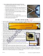
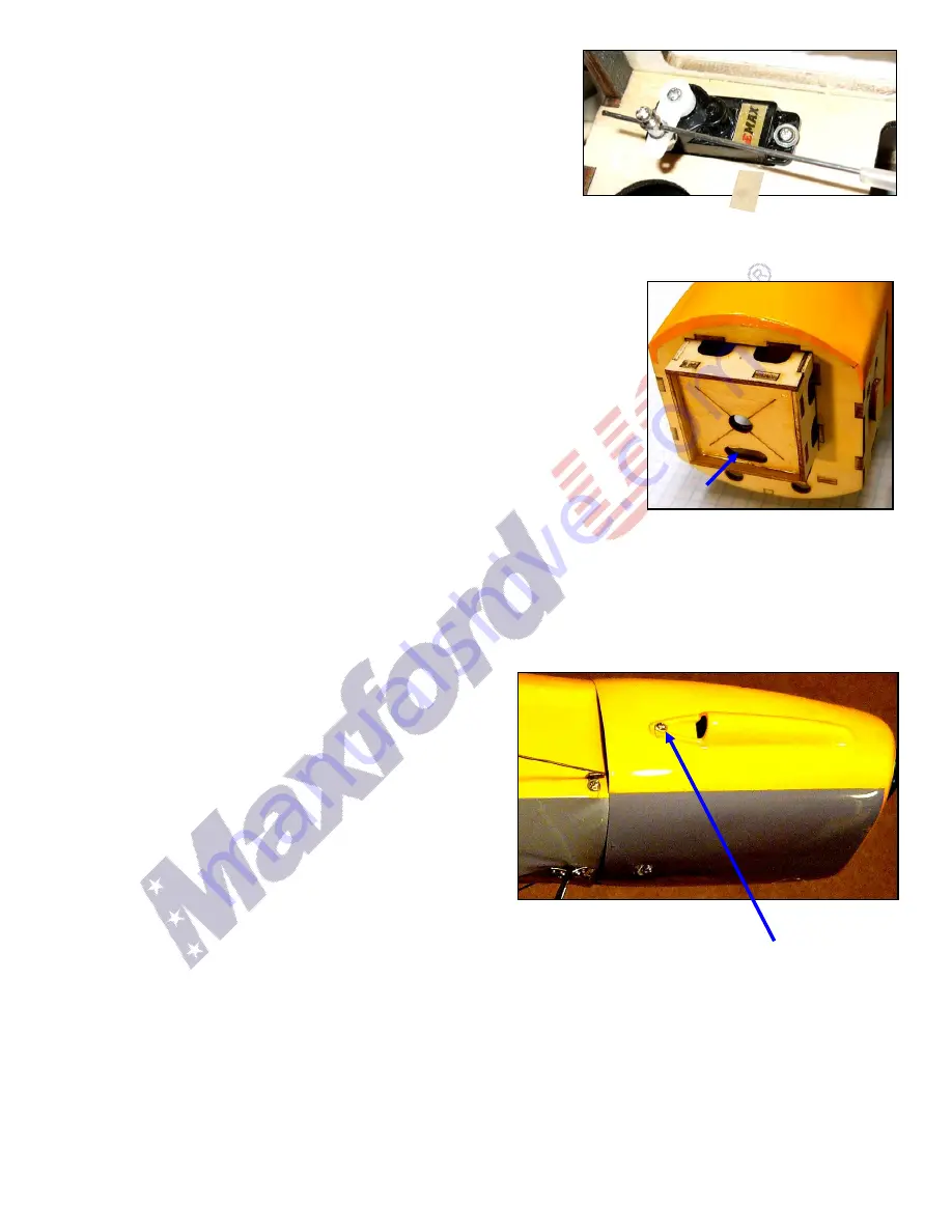
Using the motor‟s included X-mount and related hardware, attach the motor to the Storch‟s plywood motor box and
guide it‟s 3 wires into the slotted opening. Position your ESC inside the motor box and connect the motor‟s 3 wires to
the electronic speed control‟s (ESC‟s) 3 wires. Connect the ESC‟s servo-like connector to the receiver‟s throttle
channel and carefully check the motor‟s rotation-direction as follows …
a.
If you are using a computer radio, ensure the transmitter‟s „endpoint
adjustments‟ are set to their normal, full-range settings. Set your transmitter‟s
throttle and throttle trim controls to minimum. With NO PROPELLER on the
motor, switch ON the transmitter and connect the ESC to the battery. Listen
for a series of initialization sounds, then slowly raise the transmitter‟s throttle
to no more than 25% of the way up; the motor should rotate in the clockwise
direction as viewed from the rear of the airplane. (Run the motor slowly and
only for the few seconds necessary to observe its direction of rotation.) If the
motor rotated in the clockwise (correct) direction, uniquely mark each of the
3 pairs of ESC-to-motor wires to avoid repeating this test. Return your
transmitter‟s throttle to minimum, disconnect the ESC from the battery, switch
OFF the transmitter, disconnect the ESC from the motor, set aside the battery, receiver and transmitter, and proceed
to step 34.
b.
If the motor powered-up in the counterclockwise (wrong) direction as viewed from the rear of the airplane, return the
throttle control to minimum, disconnect the ESC from the battery, swap either 2 of the 3 ESC-to-motor wires, and
repeat the above step to ensure the motor rotates in the correct direction.
34.
With the motor‟s direction confirmed, slide the motor box into the firewall and reconnect the ESC to the motor and to
your receiver.
35.
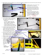
Test-fit the fiberglass cowl over the motor and install a
propeller onto the motor‟s shaft. Depending on the
dimensions of your motor, its collet, and the shape of your
propeller, slide the motor-mounting box forward or
backward and/or adjust the opening in the cowl to ensure the
motor and propeller freely rotate and nothing is touching the
front or the inside of the cowl.
36.
With the cowl and motor properly adjusted, secure the motor
box to the fuselage with glue or drive wood screws through
the open area at the bottom of the fuselage. (NOTE: Some
customers have told us they like to glue scrap wood to
reinforce the area where the motor box is attached to the
firewall on all of their 300W and larger electric-powered airplanes. This may be a good idea!)
37.
Drill a hole in each side of the cowl and use flat head screws to attach the cowl at each side the fuselage as shown
above.
38.
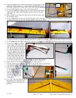
Position the tube-shaped composite wing rod into its openings in the fuselage toward the front of the cockpit. Position
the flat, rectangular-shaped composite rear joiner through the fuselage in the openings in the fuselage toward the rear
of the cockpit.
39.
Test-fit a gull-shaped winglet onto the wing rod and composite joiner to each side of the fuselage and test-fit the wing
panels onto the wing rod and into the hinge-assembly at the outside rear corner of each gull-shaped winglet.
40.
Use 5-minute epoxy to attach the winglets to the sides of the fuselage. (IMPORTANT: Be careful to NOT get any glue
on the tube-shaped composite wing rod.)
V.2-150423
Entire Contents © Copyright 2013 by Maxford USA
Slotted
opening

