


Copyright Maxford USA 2019
8.
To help ensure the security of your servo connections, we recommend
Maxford USA servo-extension safety clips
about safety clips see
http://www.maxfordusa.com/servoextensionsafetyclip.aspx
9.
Assemble any included or optionally installed
EZ-Link connectors as shown at the
When applying threadlock compound
glue the EZ-Link connector to the control arm
or mounting tab, and be careful to not
pushrods bind against any nearby surface
10.
Use your radio system or a servo tester to
to learn more about servo testers at
11.
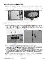
String may be supplied to pull your servo’s lead
extensions or other wiring through the
you may find it easier to use masking tape to temporarily attach
the end of the wire to a length of coat
wire to pull the lead through the airframe as
12.
After you determine each wood-screw’s location,
hole then apply thin CA adhesive to harden
13.
If Mylar hides a CA hinge’s slot, find and open the slot by carefully pressing with a fingernail or sharp
hobby knife.
14.
If you are not an experienced ARF assembler or
experienced R/C assembler and pilot.
15.
Apply threadlock compound or CA adhesive
16.
Use epoxy to permanently attach, protect
17.
If you have concern about the security of any factory
adhesive around the perimeter of such part(s) as a
18.
Production details such as included hardware and/or Mylar
19.
After adjusting any clevis, secure the clevis to its threaded rod with
threadlock compound, epoxy, or CA adhesive.
For additional safety, you may hold the clevis closed by adding
small piece of tubing (not supplied) as shown at th
(NOTE: if included with this model, clevises may be made of plastic or metal.)
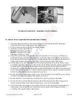
20.
Use crimp tubes to secure any included wing
threaded rods and clevises as pictured at the right
a.
Slide the crimp tube onto the cable
end of the cable through the anchor point or
hole in the end of the threaded rod.
b.
Direct the end of the cable back into and all
the way through the crimp tube.
c.
Adjust the cable’s tension, then u
the length of the crimp tube to securely crimp the tube onto the cable.
(NOTE: for your safety, after squeezing any crimp tube or
on its pushrod or threaded rod, a
secure each crimp tube or clevis
of wire poking out from the end of any crimp tube
can be sharp enough to cut or abrade skin!
21.
This model may include plastic, fiberglass and/or
sand any such part, wear safety goggles, a particle mask and rubber gloves to guard yourself from eye,
skin and respiratory-tract irritation
22.
If you use an electric power system,
OPERATING YOUR MODEL AIRPLANE’S ELECTRIC POWER SYSTEM
Page 5 of 13
the security of your servo connections, we recommend using optional
extension safety clips as pictured at the right. (For information
http://www.maxfordusa.com/servoextensionsafetyclip.aspx
.)
Assemble any included or optionally installed
as shown at the right.
lock compound, do
NOT
Link connector to the control arm
be careful to not let any
nearby surfaces.
or a servo tester to center your servos before installation. (You may
at
http://www.maxfordusa.com/servo.aspx
.)
String may be supplied to pull your servo’s leads and/or servo
through the wing or fuselage; however,
you may find it easier to use masking tape to temporarily attach
length of coat-hanger wire, then use the
wire to pull the lead through the airframe as pictured at the right.
screw’s location, drill a small guide
apply thin CA adhesive to harden and strengthen the wood where the screw
If Mylar hides a CA hinge’s slot, find and open the slot by carefully pressing with a fingernail or sharp
ARF assembler or R/C pilot, we strongly urge you to get assistance from an
pilot.
or CA adhesive to secure hardware from vibration.
, protect and reinforce critical airframe assemblies.
out the security of any factory-fabrication procedure(s), you may apply
perimeter of such part(s) as a safety precaution.
as included hardware and/or Mylar, trim, or paint colors may vary.
clevis, secure the clevis to its threaded rod with
threadlock compound, epoxy, or CA adhesive.
For additional safety, you may hold the clevis closed by adding a
small piece of tubing (not supplied) as shown at the right.
f included with this model, clevises may be made of plastic or metal.)
any included wing wires to anchor points and/or to attach
as pictured at the right:
tube onto the cable. Guide the
anchor point or
rod.
Direct the end of the cable back into and all
Adjust the cable’s tension, then use pliers to firmly squeeze several places along
the length of the crimp tube to securely crimp the tube onto the cable.
squeezing any crimp tube or adjusting any clevis
on its pushrod or threaded rod, apply epoxy or thin CA adhesive to permanently
clevis in position. Be careful to not leave any strands
of wire poking out from the end of any crimp tube; exposed small steel strands
be sharp enough to cut or abrade skin!)
plastic, fiberglass and/or carbon-fiber-reinforced parts. If you
such part, wear safety goggles, a particle mask and rubber gloves to guard yourself from eye,
tract irritation; never blow into such a part as the dust may blow back into your face.
an electric power system, read “IMPORTANT THINGS TO CONSIDER WHEN INSTALLING AND
OPERATING YOUR MODEL AIRPLANE’S ELECTRIC POWER SYSTEM” on the Maxford USA Website
Connector body
Control arm (or tab)
Washer
Mounting nut
RS190529
optional
(You may be interested
the wood where the screws are to be installed.
If Mylar hides a CA hinge’s slot, find and open the slot by carefully pressing with a fingernail or sharp
, we strongly urge you to get assistance from an
fabrication procedure(s), you may apply extra epoxy
or paint colors may vary.
attach pull-pull cables to
f you ever drill, grind or
such part, wear safety goggles, a particle mask and rubber gloves to guard yourself from eye,
part as the dust may blow back into your face.
IMPORTANT THINGS TO CONSIDER WHEN INSTALLING AND
on the Maxford USA Website at
Clamping bolt
Connector body
Control arm (or tab)
Mounting nut