


Copyright Maxford USA 2019
Page 3 of 13
RS190529
III. SPECIAL FEATURES
Classic balsa and plywood construction.
All required openings are predrilled and/or precut.
2-piece fuselage design will shrink the size of boxes, that might help to prevent shipping damage
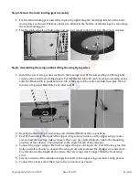
The wing is easily removed for transportion with Maxflok Pins*.
All major assemblies are preassembled and either precovered in Mylar or prepainted.
Designed for both gas and electric power.
An oversized removable cockpit hatch gives customers a wide
range of choices for using space inside the fuselage.
Sacle Anti-spin Strakes added on tail
Mylar covered ARF is painted a matt top coat at factory.
This is the only flat-finish ARF on the market. See the difference
of regular mylar covered wing panel (left) and flat-finish
result (right).
*
Maxlok Pin is the design for easy assembling of model airplane parts invented by Maxford USA. A rod will go through the two
parts, a tab will be half glued in 1st part, half slide into a slot on 2nd part. A magnet bottom will be preinstalled in the 2nd part,
a L shape metal pin will slide through the 2nd part and tab to be held by the magnet. Simply remove the pin, the 1st and 2nd
parts will be disassembled.
IV. IMPORTANT THINGS CUSTOMERS MUST KNOW BEFORE ASSEMBLING THIS ARF
Please read and follow all instructions carefully, even if you are an experienced builder. Any assembling,
testing or flying of this airplane is done entirely at your own risk. If you use a receiver battery to power
your radio system and you are using an electric power system, do not attempt to combine the output of
your radio’s battery with any battery-eliminator circuit.
V. STORAGE, FIELD SETUP & PREFLIGHT CHECKS
1.
Check the Mylar covering material’s joints and surfaces. If necessary, carefully use an iron on medium
heat to secure the edges and to tighten any loosened areas. Recheck and retighten from time to time; be
careful to not apply too much heat as you secure edges or tighten the Mylar. If any trim becomes
loosened, press it down and/or apply clear tape. Never apply heat to any trim or plastic part.
2.
Ensure the propellers are securely attached to your engines or motors and that they remain undamaged
and correctly balanced.
3.
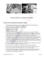
To remove the wing:
a.
Remove the bolts securing the wing to the fuselage near the trailing edge of the wing.
b.
Slide the wing a few inches toward the tail, disconnect the servo extensions and glow-plug driver
wires if used, or motor wires if using an electric power system, then lift the wing fully away from the
fuselage. If desired for transport or storage, the wing panels may also be separated and the wing rod
may also be removed. Be careful to retain the removed wing attachment bolts, any optional Maxford
USA servo-extension safety clips you may have installed, and the wing rod if removed from the wing
panels.
4.
To reinstall the wing, reverse the above procedure:
a.
If the wing panels were separated, slide the wing panels onto the wing rod. Position the wing above
the fuselage and reconnect the servo extensions, optional Maxford USA servo-extension safety clips
and any other optional wiring (or motor wires if using an electric power system).
b.
Slide the wing forward and insert the carbon fiber ‘pins’ in the leading edge of the wing into the
former at the front of the wing saddle, then use the wing attachment bolts to firmly secure the wing
to the fuselage.