6.0 TENSION CONTROL
www.maxcessintl.com
MAGPOWR Spyder-Plus-S1 Tension Control
MI 850A351 1 C
Page 18 of 68
6.3 LOAD CELL CALIBRATION (REQUIRED)
Navigate to the
Cal Sensors
menu. Press
.
Select
YES
to calibrate sensors. Press
.
Unload the sensing roll. Remove all web and weight from the sensing roller before
pressing
.
Pressing
will overwrite previous calibrations.
When
Maximum Tension
appears, press
to enter the maximum tension that will
be used on this system (if different than that displayed. This is the upper limit of the
tension range as read by the load cells. Choose a value for the Max Tension that
will have room for the highest setpoint tension you plan to run, plus any tension
errors that may occur during operation within the limits of the load cell load rating.
This setting also scales the analog bar graph. (Usually it is best to set
Maximum
Tension
to approximately twice the value of the normal running tension.) When
finished press
.
Enter the
Applied Tension
you will use to calibrate the load cells.
Press
.
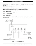
Apply the tension to the sensing roll. This tension should be applied to the sensing
roll using a rope or narrow web that is routed around the sensing roll in the same
way as the normal web. See Figure 7. This tension is best applied using a weight,
but a spring scale can also be used. Press
.
Calibration has been performed. Remove the calibration load from the sensing roll.
Figure 7. Applied Calibration Tension
6.4 TUNING (REQUIRED)
Two steps are involved.
1)
Quick Stab
to get the control loop stable if upon start-up the default
parameters do not provide a stable closed loop. See Section 6.4.1.
2)
Tuning
optimizes the Spyder by first tuning to make the system slightly
unstable; then adjusting the tuning parameters to make it stable. By doing so
the system is tuned to be as responsive as possible and still remain stable
throughout its range of operation. See Section 6.4.2.
Содержание MAGPOWR Spyder-Plus-S1
Страница 2: ......

