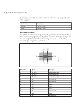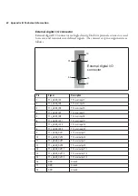
Connectors of the Matrox Morphis QxT Digital I/O module 63
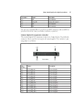
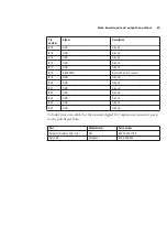
19
GND
Ground.
20
NC
Not connected.
21
GND
Ground.
22
GND
Ground.
23
GND
Ground.
24
TTL_USER_OUT0
TTL user output 0.
25
GND
Ground.
26
TTL_USER_OUT5
TTL user output 5.
27
GND
Ground.
28
TTL_USER_OUT10
TTL user output 10.
29
GND
Ground.
30
NC
Not connected.
31
TTL_USER_IN0
TTL user input 0.
32
TTL_USER_IN2
TTL user input 2
33
TTL_USER_IN4
TTL user input 4.
34
TTL_USER_IN6
TTL user input 6.
35
TTL_USER_IN8
TTL user input 8.
36
TTL_USER_IN10
TTL user input 10.
37
TTL_USER_IN12
TTL user input 12.
38
TTL_USER_IN14
TTL user input 14.
39
TTL_USER_OUT2
TTL user output 2.
40
TTL_USER_OUT4
TTL user output 4.
41
TTL_USER_OUT6
TTL user output 6.
42
TTL_USER_OUT8
TTL user output 8.
43
TTL_USER_OUT12
TTL user output 12.
44
TTL_USER_OUT14
TTL user output 14.
Pin
Signal
Description
Содержание Morphis QxT
Страница 1: ...Matrox Morphis QxT Installation and Hardware Reference Manual no 11002 101 0100 March 27 2007...
Страница 6: ......
Страница 7: ...Chapter 1 Introduction This chapter outlines the key features of the Matrox Morphis QxT board...
Страница 16: ...16 Chapter 1 Introduction...
Страница 17: ...Chapter 2 Chapter 2 Hardware installation This chapter explains how to install the Matrox Morphis QxT hardware...
Страница 26: ...26 Chapter 2 Hardware installation...
Страница 30: ...30 Chapter 3 Using multiple Matrox Morphis QxT boards...
Страница 43: ...Appendix A Glossary This appendix defines some of the specialized terms used in this Matrox Morphis document...
Страница 74: ......
Страница 76: ...Describe the problem...


