


Base board input and output connectors 57
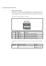
You can use a standard HD 15-pin VGA to 5BNC monitor cable (available at
your local electronic store) to interface with this connector.
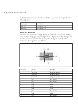
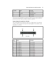
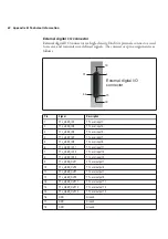
Internal digital I/O expansion connector
The internal digital I/O expansion connector is a high-density, 50-pin female
connector that is used for user input and output signals. The connector’s pin
assignment is as follows:
12
NC
Not connected.
13
VID_OUT3
Analog video output 3.
14
NC
Not connected.
15
NC
Not connected.
Pin
number
Signal
Description
A1
TTL_USER_IN0
TTL user input 0.
A2
TTL_USER_IN2
TTL user input 2.
A3
TTL_USER_IN4
TTL user input 4.
A4
TTL_USER_IN5
TTL user input 5.
A5
TTL_USER_IN7
TTL user input 7.
A6
TTL_USER_IN9
TTL user input 9.
A7
TTL_USER_IN10
TTL user input 10.
A8
TTL_USER_IN12
TTL user input 12.
A9
TTL_USER_OUT0
TTL user output 0.
A10
TTL_USER_OUT1
TTL user output 1.
A11
TTL_USER_OUT2
TTL user output 2.
Pin number
Signal
Description
B25
A25
A1
B1
Board side
Содержание Morphis QxT
Страница 1: ...Matrox Morphis QxT Installation and Hardware Reference Manual no 11002 101 0100 March 27 2007...
Страница 6: ......
Страница 7: ...Chapter 1 Introduction This chapter outlines the key features of the Matrox Morphis QxT board...
Страница 16: ...16 Chapter 1 Introduction...
Страница 17: ...Chapter 2 Chapter 2 Hardware installation This chapter explains how to install the Matrox Morphis QxT hardware...
Страница 26: ...26 Chapter 2 Hardware installation...
Страница 30: ...30 Chapter 3 Using multiple Matrox Morphis QxT boards...
Страница 43: ...Appendix A Glossary This appendix defines some of the specialized terms used in this Matrox Morphis document...
Страница 74: ......
Страница 76: ...Describe the problem...