background image

44   Appendix A: Glossary

Glossary

• Band

One of the surfaces of a buffer. A grayscale image requires just one band. A color 
image requires three bands, one for each color component.

• Bandwidth

A term describing the capacity to transfer data. Greater bandwidth is needed to 
sustain a higher transfer rate. Greater bandwidth can be achieved, for example, by 
using a wider bus.

• Bus

A pathway along which signals are sent, generally in two directions, for 
communication of data.

• CIF

Common Intermediate Format.

 A set of video formats used to standardize the 

horizontal and vertical resolutions in pixels of YCbCr sequences in video signals.

• Color component

One of the components that make up a color space. Typically, each component 
of a color image is stored in a separate band of a multi-band buffer.

• Color space

A color space is a way of representing and describing the complete range of 
perceived colors. A number of color spaces have been developed. Common color 
spaces are RGB and HSL. Both describe the same range of perceivable colors.

• D1

A digital video standard, used for storing uncompressed digitized component 
video, digital audio, and a time code. D1 video resolution is 720 x 480 for NTSC 
systems and 720 x 576 for PAL systems.

Содержание Morphis QxT

Страница 1: ...Matrox Morphis QxT Installation and Hardware Reference Manual no 11002 101 0100 March 27 2007...

Страница 2: ...damages or costs relating to the loss of profits business goodwill even if advised of the possibility of such damages In no event will Matrox and its suppliers liability exceed the amount paid by you...

Страница 3: ...tandard package 13 Optional items 13 Handling components 14 Installation overview 15 Chapter 2 Hardware installation 17 Installing Matrox Morphis QxT 18 Installing the cables for Watchdog functionalit...

Страница 4: ...atter 40 MPEG 4 compression section 41 PCIe interface 42 Appendix A Glossary 43 Glossary 44 Appendix B Technical information 47 Technical information 48 Global information 48 Acquisition features 48 M...

Страница 5: ...Appendix C Listing of Matrox Morphis QxT boards 65 Major revisions of Matrox Morphis QxT 66 Index Regulatory compliance for Matrox Morphis QxT...

Страница 6: ......

Страница 7: ...Chapter 1 Introduction This chapter outlines the key features of the Matrox Morphis QxT board...

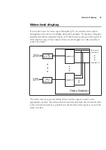
Страница 8: ...fore images are sent for compression The following diagram illustrates the data flow of the Matrox Morphis QxT board Host x4 PCIe Video capture controller Video selector Video output 0 test point Deco...

Страница 9: ...formatting features These include cropping ROI capture arbitrary downscaling to 1 16th of a field or frame and vertical horizontal flipping Grabbed images can be converted into the following formats...

Страница 10: ...ote that transfer of image data to a display board or other PCIe devices might require intervention from the Host CPU depending on your computer s architecture1 Documentation conventions When the term...

Страница 11: ...display control and archiving ActiveMIL ActiveMIL is a set of ActiveX controls that are based on MIL ActiveMIL was designed for rapid application development RAD tools such as Microsoft s Visual Basic...

Страница 12: ...p to date PCIe chipset An up to date chipset is recommended because it generally offers better performance in terms of data transfer rates To learn more about the most appropriate chipset refer to the...

Страница 13: ...dered Matrox Morphis QxT you should receive the following items The Matrox Morphis QxT base board The Matrox Morphis QxT Installation and Hardware Reference manual this document Optional items You mig...

Страница 14: ...n Matrox Morphis QxT are sensitive to static electricity and surges Improper handling can seriously damage the circuits Be sure to follow these precautions Drain static electricity from your body by t...

Страница 15: ...with MIL Lite can also be accomplished with MIL ActiveMIL ActiveMIL Lite or Matrox Inspector 1 Need help If you experience problems during installation or while using this product refer to the support...

Страница 16: ...16 Chapter 1 Introduction...

Страница 17: ...Chapter 2 Chapter 2 Hardware installation This chapter explains how to install the Matrox Morphis QxT hardware...

Страница 18: ...ching a metal part of the computer chassis Use the following steps to install your Matrox Morphis QxT board s Note that your board s should be installed before you install your software 1 Remove the c...

Страница 19: ...the cables for Watchdog functionality section later in this chapter 5 Carefully position the Matrox Morphis QxT base board in the selected empty PCIe slot Once perfectly aligned with the slot s connec...

Страница 20: ...al information 2 Create a second custom cable Cable B with a standard 0 1 spacing 2 pin female connector at one end and at the other end a connector that fits into the motherboard reset connector see...

Страница 21: ...rphis QxT Digital I O module to the computer chassis Anchor the module s bracket to the chassis using the screw that you removed in the first section 3 Connect the Matrox flat ribbon cable shipped wit...

Страница 22: ...bbon cable to the digital I O connector on the base board shown below The cable connector will latch properly only when the red wire of the cable is closest to the board s bracket Reserved Digital I O...

Страница 23: ...connect a video source to your Matrox Morphis QxT plug the HD 44M 18BNC cable into the DB 44 video input connector Connect your video sources to the BNCs at the other end of the cable The BNC connect...

Страница 24: ...g video input for acquisition path 6 CH 7 P7_VID_IN Analog video input for acquisition path 7 CH 8 P8_VID_IN Analog video input for acquisition path 8 CH 9 P9_VID_IN Analog video input for acquisition...

Страница 25: ...Digital I Omodulehasone44 pinmale I O connector on its bracket To connect an input output device to the Matrox Morphis QxT Digital I O module attach a custom built cable For more information see Appen...

Страница 26: ...26 Chapter 2 Hardware installation...

Страница 27: ...Chapter 3 Using multiple Matrox Morphis QxT boards This chapter explains how to use multiple Matrox Morphis QxT boards...

Страница 28: ...ges from video sources attached to Matrox Morphis QxT however the number of video sources from which you can simultaneously capture images is determined by the available bandwidth of your PCIe interfa...

Страница 29: ...re from different boards 29 You should not have any PCIe bandwidth problems capturing up to 16 full sized color images simultaneously from multiple Matrox Morphis QxT boards assuming you are using a h...

Страница 30: ...30 Chapter 3 Using multiple Matrox Morphis QxT boards...

Страница 31: ...Chapter 4 Hardware reference This chapter explains the architecture of the Matrox Morphis QxT hardware aswellas the available features and modes...

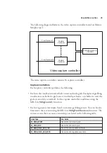
Страница 32: ...t x4 PCIe Video capture controller Video selector Video output 0 test point Decoder 1 Decoder 0 Video output 3 test point Decoder 15 Encoder 3 Encoder 0 Acquisition memory 128 MB Overlay processor Tra...

Страница 33: ...rox Morphis QxT To grab from a video source allocate a MIL digitizer with a DCF that matches the video source s data type using the MIL Lite MdigAlloc function a MIL digitizer represents the acquisiti...

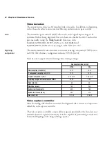
Страница 34: ...NTSC PAL format to digitized video in YUV16 4 2 2 Each decoder supports the following video timing settings Video capture controller Once the analog video hasbeen converted to digitized video itenter...

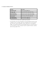
Страница 35: ...apture controller conditions using the MIL Lite MdigControl function Each can generate interrupts based on various grabbing events You can hook a function to these events using the MIL Lite MdigHookFu...

Страница 36: ...n memory sends the data to the appropriate device M_GRAB_FIELD_END Hook to the end of grabbed fields M_FRAME_START1 Hook to the start of the incoming signal s frames M_FIELD_START_ODD1 Hook to the sta...

Страница 37: ...to any of four outputs Data is sent straight to a video encoder it cannot be altered The video selector can select which of the 16 video inputs to send to the appropriate encoder The video selector ro...

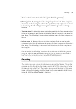
Страница 38: ...formation on the electrical specification of user defined signals see the section Electrical specifications in Appendix B Technical information Watchdog circuitry Matrox MorphisQxTintegratesWatchdog c...

Страница 39: ...a reboot the Host computer does not start regular operations before the specified interval expires the Host computer is assumed to have hung The Watchdog s reboot timer will then force the Host comput...

Страница 40: ...field or frame This can be useful to implement custom software based motion detection because at a reduced scale image comparison is faster Vertical horizontal flipping Captured data can be flipped v...

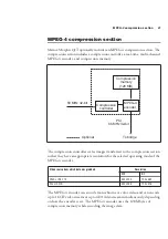
Страница 41: ...ution for the selected operating mode of the MPEG 4 encoder The MPEG 4 encoder can encode monochrome or color video and can encode up to 16 CIF video streams or up to 4 D1video streamssimultaneously d...

Страница 42: ...f the GOP The MPEG 4 encoder does not allow for manipulation of the data once it has been compressed After the data is encoded the compressed stream is then passed to the PCI to PCIe bridge PCIe inter...

Страница 43: ...Appendix A Glossary This appendix defines some of the specialized terms used in this Matrox Morphis document...

Страница 44: ...formats used to standardize the horizontal and vertical resolutions in pixels of YCbCr sequences in video signals Color component One of the components that make up a color space Typically each compon...

Страница 45: ...alf consists of the image s even lines known as the even field Frame A single image grabbed from a video camera GOP Group of Picture A group of pictures is a group of successive pictures within an MPE...

Страница 46: ...ripheral Component Interconnect Present day standard expansion bus Progressive scanning Describes a transfer of data in which the lines of the source input device are written sequentially into the des...

Страница 47: ...Appendix B Technical information This appendix contains information that might be useful when installing the Matrox Morphis QxT board...

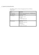
Страница 48: ...Matrox Morphis QxT are available on the Matrox website under the board s PC compatibility list Acquisition features Can simultaneously capture from up to 16 independent video sources Accepts composit...

Страница 49: ...application or system failure Supports 16 TTL user defined input signals and 16 TTL user defined output signals 5 V to control or synchronize with other devices These signals can be internally access...

Страница 50: ...er of an MPEG 4 stream to Host memory Features an on board 32 bit 66 MHz PCI bus master for the MPEG 4 encoder to reduce CPU usage Features an on board 64 bit 133 MHz PCI X bus master to reduce CPU us...

Страница 51: ...ices In addition if using multiple boards do not forget to add their total power requirements together Typical operating voltage and current for Matrox Morphis QxT no compression option and no module...

Страница 52: ...put signals Termination 75 with jumper installed 100 K without jumper Video output signals 75 termination required User input signals No termination Input current 1 A max Input voltage Low 0 0 V min 0...

Страница 53: ...Morphis QxT I O module 3 8 L x 9 5 H cm 1 5 x 3 8 Minimum maximum ambient operating temperature 0 C to 55 C Minimum maximum storage temperature 25 C to 85 C Operating humidity 10 90 non condensing Sto...

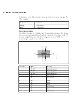
Страница 54: ...ge of the board there is a 50 pin digital I O connector for I O from the Matrox Morphis QxT digital I O module In addition there is one system reset connector Video input connector The video input con...

Страница 55: ...Ground 9 P5_VID_IN Analog video input for acquisition path 5 31 NC Not connected 10 GND Ground 32 GND Ground 11 P13_VID_IN Analog video input for acquisition path 13 33 P8_VID_IN Analog video input f...

Страница 56: ...play device for example TV monitor computer monitor that allows composite input or VCR The connector s pin assignment is as follows Manufacturer Norcomp Inc Connector 180 044 102 031 Backshell 970 025...

Страница 57: ...gnment is as follows 12 NC Not connected 13 VID_OUT3 Analog video output 3 14 NC Not connected 15 NC Not connected Pin number Signal Description A1 TTL_USER_IN0 TTL user input 0 A2 TTL_USER_IN2 TTL us...

Страница 58: ...ut 10 A21 TTL_USER_OUT11 TTL user output 11 A22 TTL_USER_OUT12 TTL user output 12 A23 TTL_USER_OUT13 TTL user output 13 A24 TTL_USER_OUT14 TTL user output 14 A25 TTL_USER_OUT15 TTL user output 15 B1 T...

Страница 59: ...Ground B14 GND Ground B15 GND Ground B16 GND Ground B17 GND Ground B18 RESERVED Reserved Do not connect B19 GND Ground B20 GND Ground B21 GND Ground B22 GND Ground B23 GND Ground B24 GND Ground B25 GN...

Страница 60: ...nment is as follows To build your own cable for the system reset connector parts can be purchased from Connector Pin Signal Description J4 1 RESET_MB Reset signal output usually to motherboard J4 2 GN...

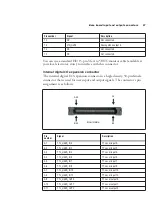
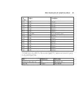
Страница 61: ...Morphis QxT Digital I O module has one connector on its bracket the external digital I O connector HD 44 The module also has one internal connector an I O expansion connector which interfaces with th...

Страница 62: ...USER_IN5 TTL user input 5 4 TTL_USER_IN7 TTL user input 7 5 TTL_USER_IN9 TTL user input 9 6 TTL_USER_IN11 TTL user input 11 7 TTL_USER_IN13 TTL user input 13 8 TTL_USER_IN15 TTL user input 15 9 TTL_US...

Страница 63: ...1 TTL_USER_IN0 TTL user input 0 32 TTL_USER_IN2 TTL user input 2 33 TTL_USER_IN4 TTL user input 4 34 TTL_USER_IN6 TTL user input 6 35 TTL_USER_IN8 TTL user input 8 36 TTL_USER_IN10 TTL user input 10 3...

Страница 64: ...ion To build your own cable you can purchase the following part This part can be purchased from third parties such as Digi Key Corporation www digikey com Manufacturer Connector Backshell NorComp Inc...

Страница 65: ...Appendix C Listing of Matrox Morphis QxT boards This appendix lists specific versions and revisions of the Matrox Morphis QxT board...

Страница 66: ...of Matrox Morphis QxT boards Major revisions of Matrox Morphis QxT Board PCB VER Description Matrox Morphis QxT board Y7250 00 rev A Original version Matrox Morphis QxT Digital I O module Y7278 00 re...

Страница 67: ...ders video 34 dimensions specifications 53 documentation conventions 10 E electrical specifications 51 environmental specifications 53 F flipping 9 40 formatting features 9 G gain 34 H hardware refere...

Страница 68: ...ts computer 12 S sampling rate 34 scaling 9 40 software supported 10 specifications dimensions 53 electrical 51 environmental 53 technical 48 system reset connectors 60 T technical information 48 Tran...

Страница 69: ...ease theseparation between the equipment andreceiver Connect the equipment into an outlet on a circuit different from that to which the receiver is connected Consult the dealer or an experienced radio...

Страница 70: ...dio interference in which case the user may be required to take adequate measures To meet EC requirements shielded cables must be used to connect the monitor and other peripherals to the card These pr...

Страница 71: ...odotti possono causare radiointerferenze nel qual caso all utente potrebbe venire richiesto di prendere le misure adeguate Per soddisfare i requisiti CEE il monitor e le altre periferiche vanno colleg...

Страница 72: ...ctroniques DEEE Se r f rer au site Web de Matrox www matrox com environment weee pour l information concernant le recyclage Deutsch Information f r europ ische Anwender Europ ische Regelungen zu Elekt...

Страница 73: ...rn the board directly to Matrox follow these steps 1 Contact Customer Support The Customer support contacts information sheet included in your package has the phone numbers for Matrox s offices Custom...

Страница 74: ......

Страница 75: ...r cards in system Software Specific Information Operating system Rev Matrox SW used Rev Compiler Rev Fill out only if you are returning a board RMA Who were you talking to in customer support Date boa...

Страница 76: ...Describe the problem...

Отзывы: