8
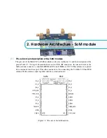
Chapter 2. Hardware Architecture - SoM module
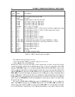
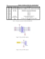
Pin
num-
ber
Name
Description
1
V3P3_LDO
3.3V output of the internal LDO
2
GND
Ground
3
VDD_RFS
Supply voltage of the radio front-end
4
LED1
Open drain output type, LED driver
5
LED2
Open drain output type, LED driver
6
LED3
Open drain output type, LED driver
7
RESET
Reset signal, active high
8
P1_6
General Purpose I/O P1_6 / NTC resistor for battery temperature sensing
9
P1_4
General Purpose I/O P1_4 / ADC1 / battery temperature sensing
10
P4_2
General Purpose I/O P4_2
11
P4_3
General Purpose I/O P4_3
12
P2_3
General Purpose I/O P2_3
13
P1_3
General Purpose I/O P1_3 / ADC2
14
P0_7
General Purpose I/O P0_7 / ADC3
15
SWD_DIO
Serial Wire Debug interface I/O signal / GPIO P0_6 / ADC4
16
SWD_CLK
Serial Wire Debug interface clock signal / GPIO P2_4 / ADC7
17
P3_3
General Purpose I/O P3_3
18
P3_4
General Purpose I/O P3_4
19
P3_2
General Purpose I/O P3_2
20
VBATT
Battery voltage input
21
GND
Ground
22
VBUS
5V supply, charging voltage
Table 2.1: USB-C connector pins description.
The module can be powered in two ways:
1. By connecting the VBATT to a battery voltage (2.7V to 4.2V).
2. By sup5V on the VBUS pin.
If both power sources are present, the battery will be charged form +5V power supply. The charging
current and charging characteristics for different battery types is software configurable. The module
provides
V3P3_LDO
voltage, it is a output of internal LDO of the DA14680 MCU, and it can be
used to supply external devices, but the maximum current drawn can’t be grater than 100mA. By
default
VDD_RFS
is connected to
V3P3_LDO
with an external 0R resistor. The current draw of
VDD_RFS
is around 35mA during transmission with +14dBm power output and around 90mA
with +17dBm power. This has to be taken in consideration when planning the power budget of
V3P3_LDO
. When even higher RF transmission power is required it is advisable to use different
power source for
VDD_RFS
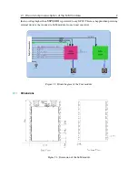
. On the Evaluation Board it can be done by using 3.3V output of the
low power converter.
The source of
V3P3_LDO
is
VBUS
when present or
VBATT
otherwise. As it is a output of a
LDO, when
VBUS
is not present, and
VBATT
drops below 3.3V the
V3P3_LDO
will follow the
battery voltage. By default all GPIO are referenced to
V3P3_LDO
(it is also possible to configure
1.8V as the GPIO level, each GPIO can be configured individually) so care must be taken to ensure

