6.3 Software development under Windows OS
31
6.3
Software development under Windows OS
The easiest way to install and configure all required tools is to install Dialogs SmartSnippets Studio
package (it can be downloaded from the company website after registration). Experienced users can
try to install all cross-compilation tools and configure they favorite SDE manually, but using Dialogs
software the whole process is straight forward. Please follow UM-B-057 User Manual from Dialog
for details about the installation.
After successful installation of SmartSnippets Studio and J-Link programmer, you should
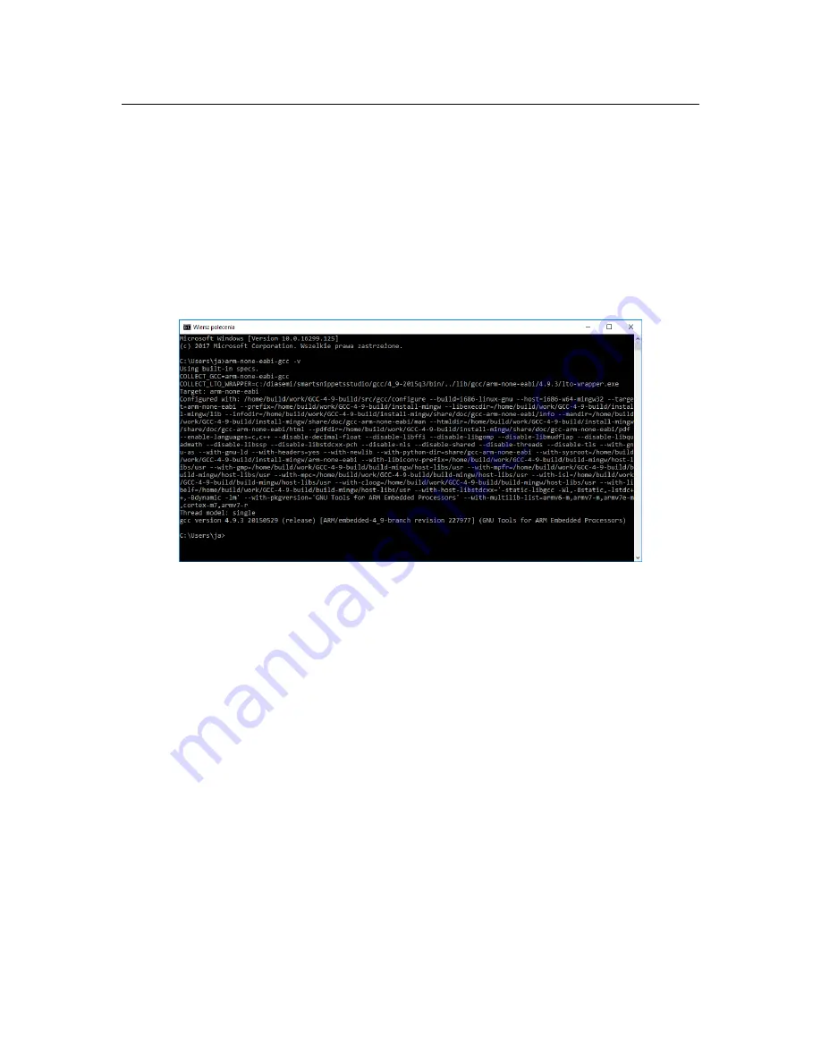
have gcc cross-compilation tools installed and proper PATH entry should exist, to check it you can
open command line window and type
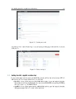
arm-none-eabi-gcc -v
The result should be similar
to what is shown on Figure 6.1. In these example we are using gcc version 4.9.3 20150529.
Figure 6.1: Checking ARM tools installation.
Download the Dialog’s Semiconductor SmartSnippets DA1468x SDK (in the example the SDK
version 1.0.8.1050.1 has been used) and MatchX Dev Kit Frmware. Both SDK and Dev Kit Firmware
should be put in one folder (for example SmartSnippet workspace folder). DKF folder contains
a make file which can be executed by navigating to the firmware folder and typing
make
in the
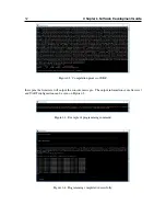
command line window. This command will compile the firmware. If everything has been setup
correctly the compilation process should return no errors and a binary file should be generated as a
result, see Fugure 6.2.
After the software has been successfully compiled it can be programmed through J-Link pro-
grammer using a script provided by Dialog Semi. In command line window navigate to the DKF
folder. The programming script
initial_flash.bat
should be located in SDK folder:
DA1468x_SDK_BTLE_v_1.0.8.1050.1\utilities\scripts\suota\v11\
It takes two parameter - path to the .bin file with firmware and path to the J-Link tools. The syntax is
as follows:
{Path}\initial_flash.bat "{Path to firmware}" "{Path to J-Link}"
The example of the command can be seen on Figure 6.3. Before executing it the Dev Kit board has
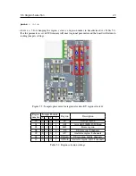
to be powered on and J-Link programmer has to be connected to SWD port on J101. Only GND,
SWDCK and SWDIO are necessary to program the board. After successful programming process
the screen should look similar as on Figure 6.4. On default DKF configures pins 5 and 6 on the
J102 connector to be UART TX and RX respectively. By connecting a UART-to-USB converter to


