14
Chapter 3. Hardware Architecture - Evaluation Board
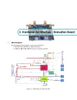
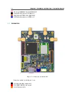
MatchX SoM is the core of the Dev Kit. It is responsible for controlling the SIMCom module,
accessing the sensors, I/O expender, RGB LED etc. It also controls different power rails enabling
low power modes.
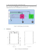
The Dev Kit can be powered by USB-C +5V and/or Lithium-ion battery connected to X401
connector.The presence of +5V is signaled by a red LED next to USB-C. When both +5V and battery
are present the MatchX SoM will start to charge the battery. The battery type, charging current, and
charging curve are software configurable.
MatchX SoM provides
V3P3_LDO
output, which is a low current output of internal LDO
capable to deliver up to 100mA of current. As it is used to power the LoRa RF front-ent by default,
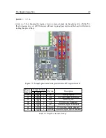
it can be used to power just very low power peripherals. If more current is needed, a onboard SMPS
TPS62740 should be used. It outputs a 3.3V up to 300mA current. Its output should be connected to
the
V3P3
power rail with the J402 jumper in position 1-2.
The SIMCom module is optional and is not included in a standard package but all peripheral
components are already soldered. The main communication interface between MatchX SoM and
SIMCom module is UART together with two control lines (SIM_NRST and SIM_PWR_KEY).
Please refer to SIMCom SIM7000E datasheet to find more information about the modules operation.
The SIM7000E is powered from +5V provided by USB-C connector which is converted to 3.3V by a
LDO. Its enable pin can be controlled by a SoM or can be always set high by a jumper.
The Dev Kit offers two ways to receive GPS signal. One is by using aforementioned SIM7000E
module. A cheaper and less power demanding alternative is using SIM28ML.

