2. Hardware Architecture - SoM module
2.1
Pin-out and pin description of the SoM module
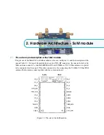
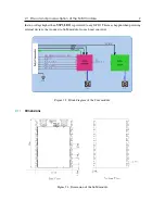
The pin-out of the MatchX Core SoM module can be seen on Figure 2.1 and the description of the
pins in Table 2.1. On top of the module there are two UF.L RF connectors, the one on the left is the
LoRa antenna connector, a suitable 868MHz in EU and 915MHz in US, 50 Ohm antenna is expected
to be connected on these port. The other connector is for connecting the 2.4GHz, 50 Ohm BLE
antenna. Both antennas come together with the evaluation board.
Figure 2.1: Pin-out of the SoM module.


