3.3 Connectors
19
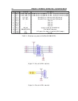
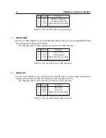
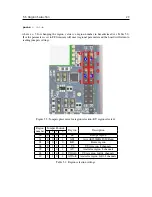
The J103 connector, shown on Figure 3.7, exposes all pins available on the PCA6416A I2C I/O
expander. It offers 16 I/Os organized in two ports P0 and P1. Each pin can be configured individually
as a input or output, and its state can be read and set by the I2C commands. Additionally there is a
interrupt line EXP_INT that is being driven by the PCA6416A when input IO changes it state.
Figure 3.7: Pin-out of J103 connector.
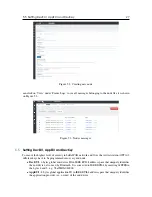
The J201 connector, depicted on Figure 3.8, exposes all unused pins of the SIMCom SIM7000E
module. For more information about the signals functions please refer to the modules datasheet.
Figure 3.8: Pin-out of J201 connector.

