Masdaf UKM-50 Скачать руководство пользователя страница 6


Mas Grup


Damages caused in transport 

 
Check the pump when it is delivered to you. Please let us know of there is 
any damage. 
 

5.2. Storage 


Please keep the unit clean and dry area during storage. 


If the pump is out of use for a long time, please consider the instructions 
below. 
1. If there is water inside the pump, drain it. 
2. Clean  the  pump  casing  and  impeller  by  jetting  clean  water  for  a  short 

time. 

3. Empty water inside the pump casing, suction line and discharge line. 
4. Add  small  amount  of  antifreeze  inside  the  pump  casing  if  it  is  not 

possible to empty it completely.  Rotate the pump shaft by hand to mix 
the antifreeze. 

5. Add  liquid  lubricator  into  the  bearing  and  seal  gap  up


until  the  level 

indicator. 

6. Close the suction and discharge exits with gasket. 
7. Spray an anti-corrosive into the pump casing. 
8. Rotate the pump shaft by hand once in every month, in order to protect 

it from freezing and to lubricate the bearings. 


6.  ASSEMBLY / INSTALLATION


6.1. Installation 


In our standard production, the pump and the motor have been installed 
in a common base plate. 

 
6.1.1. Location of Installation 


Pump  will  be  installed  in  a  location  where  the  control  and  the 
maintenance  of  the  pump  are  easily  made.  The  pump  room  should  be 
suitable  for  operation  of  lifting  systems  such  as  freight  elevator,  forklift, 
etc. 


6.1.2. Location of Installation- Local Ambient Temperature 
 

When  the  local  ambient  room temperature  exceeds  +40

o

C  in a  pumping 

system,  suitable  ventilation  should  be  provided  in  order  to  remove  the 
heat dissipated to the environment and supply fresh air. 


6.2. Type of Connection 


Type of connection depends on the design type and the size of the pump 
and  the  motor,  as  well  as  the  local  installation  conditions.  Foot-mounted 
horizontal pump-motor units have been installed in a common base plate. 


6.3. Foundation 


6.3.1. General 


In  applications  where  a  trailor  is  not  used,  the  pump  must  be  properly 
fixed to solidified concrete base plate with studs. 
Base  plate  of  the  pump  must  be  grouted.  The  foundation  shall  be  of 
concrete or steel framework. 

Note:

  The  foundation  shall  distribute  the  weight  of  the  pumping  group 

evenly. 


6.3.2. Main Properties of the Steel Framework Bases 


Foundations  with  steel  framework  shall  be  designed  in  such  a  way  that 
the base plate is bolted or welded contacting to all area. 


CAUTION 


If base plate is supported from only four points, pump group will 

stay in the middle, causing misalignment of the coupling and 

increasing the noise level. 


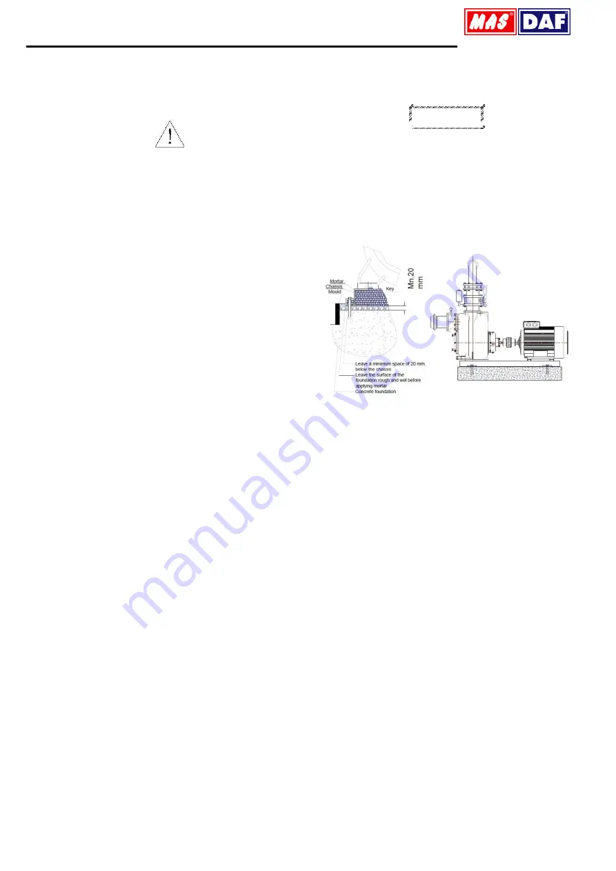
6.3.3. Foundation Properties 

The foundation shall be horizontal, flat and clean and shall support all the 
weight. 


Note:

 Reinforced concrete bases are constructed from standard concrete 

with at least B 25 resistance class. 


Figure 3:

 Typical Concrete Foundations 

 
6.4. Coupling Alignment 


6.4.1. General 


For a proper operation of a pump group, a good alignment of the coupling 
is  necessary.  Vibration,  noise,  overheating  of  the  bearings,  overcharge 
problems  can  be  attributed  to  the  misalignment  of  coupling  or  using  an 
improper coupling. 

Flexible coupling does not correct the axial misalignments between 
the  pump  and  the  motor  axes.  However,  it  allows  pinpointing  the 
misalignments. 
In  order  to  avoid  overheating,  vibration,  noise  and  wearing  of  the 
rolling bearings, alignment of the coupling has to be made properly 
and checked often. 
Do not use a different coupling other than the original type installed 
on pumping group. 


6.4.2. Method of Coupling Alignment  


When the motor moves towards the pump, a gap must be maintained in 
order  that  the  two  faces  of  the  coupling  do  not  touch  each  other.  The 
recommended  distance  is  3  mm.  To  check  the  coupling  alignment,  a 
conical measurement device and a gauge stick are needed. 


1. Angular Misalignment (Figure 4) 

In  order  to  control  the  angular  misalignment,  the  distance  between  the 
two  halves  of  the  coupling  is  measured  in  both  horizontal  and  vertical 
planes. Measurements taken at four points shall be in agreement for the 
alignment. 


2. Parallel Axis Misalignment (Figure 4)


In order to control parallel axis misalignment, a smooth edged 
gauge  stick  is  pressed  axially  over  the  upper  half  of  the  coupling. Then, 
the  gauge  stick  is  checked  for  the  other  half  of  the  coupling.  For 
alignment,  the  gauge  stick  shall  be  in  contact  with  both  of  the  halves  at 
the  same  time.  This  procedure  shall  be  repeated  for  four  sides  of  the 
coupling.  (i.e.  top,  bottom,  left  and  right  sides  of  the  coupling). When  all 
four  sides  give  reasonably  accepted  results,  alignment  of  the  coupling 
has been ensured. 

Содержание UKM-50

Страница 1: ...Revision No 02 July 2018 Self Priming Centrifugal Pumps UKM S SERIES OPERATING MANUAL...

Страница 2: ...with drivers Elektrikli Pompa niteleri Related Directives Y netmelikler 2006 42 EC Machinery Directive 2006 42 AT Makine Emniyeti Y netmeli i 2014 35 EU Low Voltage Directive 2014 35 AB Al ak Gerilim...

Страница 3: ...against the electrical risks Sign for the operator s safety 1 IMPORTANT SAFETY PRECAUTIONS In order to minimize the accidents during the mounting and putting into service of the pump the following ru...

Страница 4: ...ual If the personnel do not have enough knowledge required training must be given by the costumer If training support is needed by the costumer it will be provided by the manufacturer seller CAUTION U...

Страница 5: ...cifications of electrical motor Isolation class F Protection class IP 54 IP 55 Frequency 50 Hz Running type S1 Start up type Up to 4 kW 3x380 V Y More than 4 kW 3x380V Y 4 2 2 Coupling and Coupling Gu...

Страница 6: ...roperties of the Steel Framework Bases Foundations with steel framework shall be designed in such a way that the base plate is bolted or welded contacting to all area CAUTION If base plate is supporte...

Страница 7: ...e sure that a suitable spacing is left between the coupling halves while mounting pump and the rotor 5 Horizontal pump groups mounted on the base plate or directly mounted on the base alignment of the...

Страница 8: ...n line If there is a liquid flow from an open pipe into sump the flow should be kept away from the suction inlet because the inflow will carry air down into the sump and air entering the suction line...

Страница 9: ...e of the pump must be open to the atmospheric pressure through a by pass line installed between the pump discharge and the check valve A self priming centrifugal pump will not prime if there is suffic...

Страница 10: ...e seal bed plug it is concluded that the seal is leaking UKM S 2 x2 0 6 liter UKM S 3 x3 0 6 liter UKM S 4 x4 0 7 liter UKM S 6 x6 0 7 liter UKM S 8 x8 2 7 liter UKM S 10 x10 2 7 liter Table 4 The Mec...

Страница 11: ...embly and repair consult the literature supplied with the power source or contact your local power source representative CAUTION Before attempting to disassemble or service the pump 1 Familiarize your...

Страница 12: ...t oil bath electric oven or hot plate may be used to heat the bearings Bearings should never be heated with a direct flame or directly on a hot plane Note Hot oil is used to heat the bearings hot the...

Страница 13: ...w After the rotating assembly is installed in the pump casing coat the threads of the capscrew with Never Seez or equivalent compound and install the impeller washer and capscrew torque the capscrew t...

Страница 14: ...t 1 1 2 2 2 3 30 Impeller kit 1 1 1 2 2 3 30 Wearing Plate 2 3 4 5 5 6 60 Bearings kit 1 1 2 2 3 4 50 O Ring for Casing kit 1 1 1 1 2 2 3 40 O Ring for Shaft kit 1 1 2 2 3 4 50 Sealing Bushes kit 1 1...

Страница 15: ...needed Replace worn or damaged parts Check that impeller is properly centered and rotates Free impeller of debris Check driver output check belts or couplings for slippage Install by pass line Measur...

Страница 16: ...00 293 250 440 400 20 38 110 UKM S 6 x6 DN 150 DN 150 414 490 904 62 258 310 929 447 281 585 525 20 38 127 UKM S 8 x8 DN 200 DN 200 406 615 1021 336 388 1048 521 305 705 635 22 45 170 UKM S 10 x10 DN...

Страница 17: ...Plug 373 Washer 20 Impeller 264 Pipe Plug 374 Washer 30 Bearing Housing 265 Pipe Plug 375 Washer 35 Bearing Cover 266 Pipe Plug 377 Washer for Impeller Cap Screw 60 Shaft 267 Pump Casing Drain Plug 3...

Страница 18: ...ing Plate 211 Key for Pump Shaft 377 Washer for Impeller Cap Screw 08 Impeller Back Plate 220 Oil Gasket 390 Ring 11 Elbow Cover 221 Oil Gasket 391 Ring 12 Bearing Housing Flange 260 Pipe Plug 394 Elb...

Страница 19: ...Hex Bolt 02 Volute Casing 321 Hex Bolt 04 Flap Valve Casing 322 Hex Bolt 12 Adaptor 340 mbus Bolt 20 Impeller 360 Casing Nut 60 Shaft 370 Washer for Impeller Cap Screw 91 Suction Flap 380 Setscrew 21...

Страница 20: ...Key for Pump Shaft 391 Ring 220 Oil Gasket 400 O Ring 221 Oil Gasket 402 O Ring 222 Oil Gasket 412 Gasket 250 Mechanical Seal 413 Gasket Table 13 Rotating Region of UKM S Self Priming Centrifugal Pump...

Страница 21: ...Mas Grup 19 17 UKM S DRAWING FOR DISMANTLING Figure 18 UKM S Drawing For Dismantling...

Страница 22: ...3 x3 4 x4 6 x6 8 x8 15 Figure 14 UKM S Sectional Drawing 10 x10 16 Figure 15 UKM 50 Sectional Drawing 17 Figure 16 Rotating Region of UKM S Self Priming Centrifugal Pump Sectional Drawing 18 Figure 17...

Страница 23: ...o 17 Tuzla STANBUL TURKEY Tel 90 216 456 47 00 pbx Fax 90 216 455 14 24 Ankara Regional Directorate A a ve ler Mah 1329 Sok No 6 9 ve ler ANKARA TURKEY Tel 90 312 472 81 60 67 Fax 90 312 472 82 51 Fac...

Отзывы: