255
-
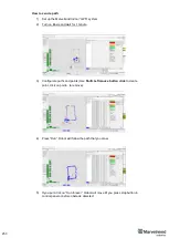
Example of proper positioning of the mobile beacon can be found here:
-
The beacon is placed horizontally and above other objects that can cast a shadow on the
stationary beacons
-
Keep the radio signal’s strength under control
-
The RSSI (Dashboard => right menu) of any beacon/modem must not be higher than -
25dBm. Otherwise, the system may malfunction
-
It is recommended the distance between the modem and beacons be no less than 0.5
–
1m. Beacons can be placed as close to each other as needed. If a beacon is extremely
close to the modem, disconnect the antenna from the beacon. Monitor the Received
Signal Strength Indicator (RSSI). It must be in the range of -25 to -70dBm. An RSSI of
less than -70dBm will work too, but packet losses may start occurring. The quality of the
radio connection very much depends on external interference as well because the used
band is ISM (either 915MHz or 433MHz) and there are numerous co-existing systems.
-
Use 30 - 50 periods (pulses) in settings instead of the default 5. Select:
-
Ultrasound settings => Number of periods
-
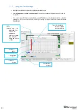
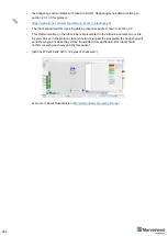
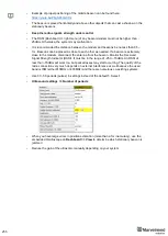
When you have large errors in position estimation (more than a 1m inaccuracy), use the
embedded Oscilloscope on
Dashboard => View
to determine which stationary beacon is
jammed
-
Reduce the gain of the ultrasonic manually depending on your system
Содержание IA-04-2D-Badge
Страница 1: ...Marvelmind Indoor Navigation System Operating manual v2022_08_24 www marvelmind com ...
Страница 18: ...18 Here is a tutorial video about architectures Help Inverse Architectures IA vs Non Inverse Architectures NIA ...
Страница 21: ...21 Beacon Mini TX Beacon Industrial RX Beacon Industrial TX Metal ...
Страница 22: ...22 Industrial Super Beacon Plastic ...
Страница 34: ...34 The equipment should be installed and operated with minimum distance 20cm between the radiator your body ...
Страница 36: ...36 Figure 2 Super Beacon with two External Microphones connected Figure 3 Super Beacon with Omni ...
Страница 39: ...39 Figure 7 One External Microphone connection Figure 8 Two External Microphone connection ...
Страница 44: ...44 Figure 3 One external microphone soldering Figure 4 Two external microphones soldering ...
Страница 46: ...46 Figure 7 Two External Microphones final view Figure 8 Two External Microphones final view ...
Страница 118: ...118 6 6 28 The system is now fully operational ...
Страница 132: ...132 7 9 1 2 Advanced settings TBD TBD TBD TBD TBD TBD If modem lost connection it restarts by itself TBD TBD TBD TBD ...
Страница 157: ...157 Example 4 No handover zone 10 11 12 14 Service zones not cross NO HANDOVER ZONE CREATED NO HANDOVER BETWEEN SUBMAPS ...
Страница 163: ...163 Move submaps as you wish Use CTRL and mouse roll to rotate Submap Awake mobile beacons It will apeare in a map ...
Страница 169: ...169 To turn on one of the mic in a specific pair press on a specific box below RX2 RX4 with CTRL ...
Страница 180: ...180 Floor 5 is enabled Floor 4 is enabled ...
Страница 190: ...190 Z X ...
Страница 207: ...207 Choose color and press OK Color applied Now background matches floorplan ...
Страница 209: ...209 Choose any color which suits you and press OK Now the hedgehog and its tracking path will be colored ...
Страница 214: ...214 9 24 IMU axis positioning Super Beacon IMU axis positions HW v4 9 IMU axis positions ...
Страница 215: ...215 Mini TX IMU axis positions Mini RX beacon IMU axis positions ...
Страница 219: ...219 Real time player turned on ...
Страница 222: ...222 10 1 Super beacon external interface pinout top view 4x4 pinout for Super Beacon 4x4 pinout for Super Beacon 2 ...
Страница 223: ...223 10 2 Beacon HW v4 9 external interface 4x4 pinout top view ...
Страница 224: ...224 10 3 Modem HW v4 9 external interface pinout top view ...
Страница 232: ...232 If everything done correctly Own IP address will change Static IP settings completed ...
Страница 238: ...238 How to change modes Choose hedge Go to Ultrasound TDMA mode Left Click to change ...

