background image

P/N 286172-00

09.08 TAP/M

Содержание BL3200

Страница 1: ...Owner s Operator s Manual Completely read and understand this manual before using this product BL3200 ...

Страница 2: ...CONTENTS SPECIFICATIONS Models Length Width Height 1 Dry Weight 1 Engine Displacement Fuel Tank Capacity Carburetor Ignition System 325 255 370mm 30 1cm 3 0 5R Walbro Diaphragm Type Solid State BL3200 4 4 kg Reverse2 Start Use only non leaded regular gasoline 2 Cycle oil mix 25 1 ratio must be approved for air cooled engines 13m s 2 NGK BPMR6Y 0 6 0 7mm Fuel Mixture Starter Vibration Level Handle ...

Страница 3: ...CT DESCRIPTION AIR INTAKE SCREEN HANDLE FAN COVER THROTTLE TRIGGER PIPE B PIPE A THROTTLE SETTING LEVER MODEL BL3200 FUEL TANK RECOIL STARTER ENGINE AIR CLEANER SERIAL NUMBER ON THE TOP OF CRANKCASE STOP SWITCH ...

Страница 4: ...ontact may cause burns During use and for some time after stopping the engine the engine is very hot Do not touch engine components such a cylinder muffler and engine covers until the engine has cooled to ambient temperature Always use A protective helmet Ear protection Protective glasses or visor Moving parts Warning Contact with rotation fan or other moving parts could cause serious personal inj...

Страница 5: ...pecial attention OPERATOR SAFETY 1 Read and understand this Owner s Operator s Manual before using this product Be thoroughly familiar with the proper use of this product 2 Never allow children to operate the Handheld Blower It is not a toy Never allow adults to operate the unit without first reading the Operator s Manual 3 Always wear eye protection 4 Wear hearing protection 5 Always wear sturdy ...

Страница 6: ...highly flammable and must be handled and stored carefully Use a container approved for storing gasoline and or fuel oil mixture 2 Mix and pour fuel outdoors and where there are no sparks or flames 3 Do not smoke near fuel storage containers or the Handheld Blower Do not smoke while operating the Handheld Blower 4 Do not overfill the fuel tank Stop filling 6 13 mm 1 4 1 2 inch from the top of the t...

Страница 7: ...op the machine quickly in an emergency For information on how to stop the engine refer to the Starting and Stopping Procedures on page 10 12 Do not point the Handheld Blower nozzle in the direction of people or pets OPERATING TECHNIQUES 1 Operate power equipment only at reasonable hours not early in the morning or late at night when people may be disturbed Comply with the times listed in local ord...

Страница 8: ... PIPES INSTALLATION 1 Align groove in pipe A with pegs on blower housing and slide pipe A on to housing 2 Rotate pipes A clock wise to lock it into place 3 Align groove in pipe B with pegs on pipe A and slide pipe B until proper position 4 Align groove in pipe B with pegs on pipe A and slide pipe B until proper position 1 Peg 2 1 3 2 4 WARNING Stop the engine before installing or removing blower p...

Страница 9: ...ains gasses that can build up pressure inside a gas tank WHAT CAN HAPPEN Fuel can be sprayed on you when removing fuel tank cap HOW TO AVOID THE HAZARD Remove fuel tank cap slowly to avoid injury from fuel spray DANGER POTENTIAL HAZARD In certain conditions gasoline is extremely flammable and highly explosive WHAT CAN HAPPEN A fire or explosion from gasoline can burn you others and cause property ...

Страница 10: ...nt of gasoline Close the container tightly and shake it momentarily to evenly mix the oil and the gasoline before filling the fuel tank on the Handheld Blower When refilling the Handheld Blower fuel tank clean around the fuel tank cap to prevent dirt and debris for entering the tank during cap removal Always shake the premix fuel container momen tarily before filling the fuel tank Always use a spo...

Страница 11: ...the following pro cedure 1 Pump the primer bulb at the bottom of the carburetor until fuel can be seen flowing through the fuel return line to the fuel tank Flowing fuel should be almost clear not foamy or full of bub bles 2 Move the choke lever to the closed position 3 Move the stop switch to the ON posi tion 4 1 Press the throttle trigger 2 Move the throttle setting lever to half position 3 Rele...

Страница 12: ...engine starts HOT RESTART To start the engine that is already warmed up hot restart or if the ambient temperature exceeds 20 C 1 Pump the primer bulb at the bottom of the carburetor until fuel can be seen flowing through the fuel return line to the fuel tank 2 Move the choke lever to the position and move the stop switch to the ON position 3 More the throttle setting lever to the idle position and...

Страница 13: ...the engine idle speed Turn the screw out counterclockwise to decrease the engine idle speed If idle speed adjustment is necessary and after adjustment the engine stalls stop using the Handheld Blower imme diately Contact your local authorized Maruyama Dealer for assistance and servicing Idle Speed Adjuster Screw WARNING Idle speed adjustment should be checked each time the unit is operated WARNING...

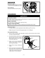
Страница 14: ...t be performed by a dealer or service center authorized by Maruyama The use of parts that are not equivalent in performance and dura bility to authorized parts may impair the effectiveness of the emission control system and may have a bearing on the outcome of a warranty claim AIR FILTER Maintenance Interval The air filter should be cleaned and inspected each time the Handheld Blower is used or mo...

Страница 15: ...fuel filter is attached to the end of the fuel pick up hose inside the fuel tank To replace the fuel filter 1 Make sure the fuel tank is empty 2 Remove the fuel cap 3 Using a wire hook gently pull the fuel fil ter out through the fuel filler opening 4 Grasp the fuel hose next to the fuel filter fitting and remove the filter but do not release the hose 5 While still holding on to the fuel hose atta...

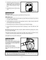
Страница 16: ...ance Interval The cylinder cooling fins should be cleaned after every 25 hours of operation or once a week whichever comes first Air must flow freely around and through the cylinder cooling fins to prevent engine over heating Leaves grass dirt and debris buildup on the fins will increase the operating temper ature of the engine which can reduce engine performance and shorten engine life Cooling Fi...

Страница 17: ...ling fin cleaning 4 Remove the two screws retaining the muffler 5 Remove and clean the tail gasket and spark arrester with a safety solvent and a stiff brush If any part cannot be thor oughly cleaned it must be replaced 3mm Allen Wrench Tail Spark Arrester Muffler ENGINE SCREEN Maintenance Interval The screen should be cleaned and inspect ed each time the Handheld Blower is used Screen Cleaning Cl...

Страница 18: ...ing 4 Remove the spark arrester see spark arrester maintenance Clean the muffler with a stiff brush IMPORTANT Be careful not to allow any dirt or debris to fall into the exhaust port as this can cause engine damage 5 Reinstall the spark arrester and tail onto the muffler then reinstall and tighten the two screws The hole of tail must be located in left see spark arrester maintenance 6 Reinstall th...

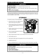
Страница 19: ...ve the spark plug and squirt a very small amount of oil into the cylinder 6 Pull the starter grip once 7 Slowly pull the starter grip to bring the piston to the top of the cylinder TDC 8 Reinstall the spark plug 9 Store the Handheld Blower in a dry place away from excessive heat sparks or open flame WARNING POTENTIAL HAZARD When engine is running fan is rotating and other parts are moving WHAT CAN...

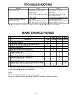
Страница 20: ...m Cause Action Engine Will Not Start STOP switch set to off position Move switch to on position Empty fuel tank Fill fuel tank Primer bulb wasn t pushed enough Press primer bulb until fuel flows through fuel return line Engine flooded Use warm engine starting procedure Engine Lacks Power or dropped Dirty air filter Clean or replace air filter down when blowing Clogged spark arrester or exhaust por...

Страница 21: ...P N 286172 00 09 08 TAP M ...

Отзывы: