Marshall Electronics V-R185-DLW Скачать руководство пользователя страница 7

30

Specifications

PANEL

Screen Size

18.5” Diagonal

Display Area (h x v)

409.8 x 230.4 mm

Pixels

1366 x RGB x 768

Viewing Angle (h x v)

178° x 178°

Brightness

300 cd/m2

Contrast Ratio

1000:1

Pixel Pitch (h x v)

0.100 x 0.300 mm

CONNECTORS

Video Input

3G-SDI 


2 x BNC Female (75 Ω) 

Video Output (Active Loop-Through)

3G-SDI 


2 x BNC Female (75 Ω) 

DVI Input

DVI-I

1 x DVI-I Female Connector

Power Input

4-Pin XLR Connector

Tally / GPI Hardware Interface

HD-15 Female

RS-422/485 Interface

2 x RJ12 (Modular 6P6C

)

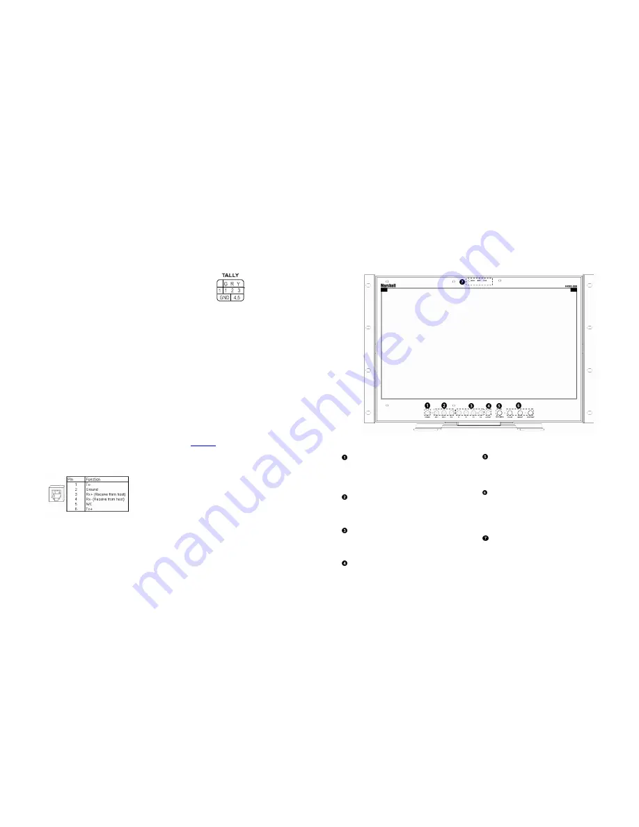
TALLY Hardware Interface (HD-15)

Activation requires contact closure of pin to ground
on the HD-15 connector:

ELECTRICAL

Power Consumption

2.0A @ 24VDC (48 W)

Voltage Requirement

24 VDC

Pinout

Pin 1:

-

Pin 2: N/C
Pin 3: N/C
Pin 4:

+

MECHANICAL

Weight (with rack ears): 8.60 lbs

Operating Temperature 32°F to 104°F (0°C to 40°C)
Storage Temperature

-4°F to120°F (-20°C to

50°C)

See

Dimensions

section for exact specifications.

.

Protocols: Image Video, TSL v4.0, MEI

7

Top and Front Panel Features

Power Button

Use the power button to toggle between ON and STANDBY

modes. The LED on the POWER button will illuminate fully
when the unit is in STANDBY mode. The LED will dim when
the unit is ON.

Input Select Buttons (SDI 1, SDI 2, DVI)

Use the SDI 1, SDI2 and DVI buttons to select the
corresponding video input. Accepted video standards are
automatically detected.

User-Definable Function Buttons

Four user-definable function buttons can be used for direct
access to various settings. Functions are assigned using the on-
screen menu.

Layout Button

Use the Layout button to switch between the four available
layouts on the monitor. See the Layouts section for more
information the available l ayouts.

RotoMenu

Knob

The RotoMenu

knob allows for accessing and navigating the

main menu using only a single knob.

Image Adjustment Knobs

Use the image adjustment knobs to adjust color brightness,
color-saturation, tint, and contrast of the image. The status of
each image adjustment parameter is shown on the bottom left

of the screen, with values ranging from 0 to 100. Default value
is 50.

LED Tally

Three LED tally lights (yellow, red, green) are available above

the screen.

Содержание V-R185-DLW

Страница 1: ...El Segundo CA 90245 Tel 800 800 6608 310 333 0606 Fax 310 333 0688 www LCDRacks com sales lcdracks com Marshall Electronics Model No V R185 DLW 18 5 DLW Desktop and Rack Mount Dual Link Waveform Monit...

Страница 2: ...ntainer for a period of one year from the purchase date This warranty is extended to the first consumer only and proof of purchase is necessary to honor the warranty If there is no proof of purchase p...

Страница 3: ...ATION 10 Using the RotoMenu knob 10 Marker Setup Submenu 10 Video Config Submenu 12 Color Config Submenu 16 System Config Submenu 16 OSD Config Submenu 18 IMD Config Submenu 21 IMD Fixed Config Submen...

Страница 4: ...4 33...

Страница 5: ...angle Adequate ventilation is required when installed to prevent possible damage to the monitor s internal components Please see the Dimensions section for more information A VESA standard 75mm hole p...

Страница 6: ...6 31 Dimensions...

Страница 7: ...s Power Button Use the power button to toggle between ON and STANDBY modes The LED on the POWER button will illuminate fully when the unit is in STANDBY mode The LED will dim when the unit is ON Input...

Страница 8: ...onnector The LED tally can be activated via the HD 15 connector by connecting the corresponding pin to ground A variety of external devices can be used to perform the contact closure The HD 15 connect...

Страница 9: ...video standards are supported by the V R185 DLW SDI Inputs 525i 625i 50 720p 29 97 30 50 59 94 60 1080p 23 98 23 98sF 24 24sF 25 29 97 30 1035i 59 94 60 1080i 50 59 94 60 3G Level A and Level B YCbCr...

Страница 10: ...the desired maximum for the Limit display of the waveform monitor Any Waveform data that goes beyond this Limit Max will be displayed in red Limit Min Use this to set the desired minimum for the Limi...

Страница 11: ...y or switching marker settings from the menu will automatically enable the markers 16 9 Markers Use this setting to superimpose one of 10 markers on the screen when in 16 9 or Full Screen mode This se...

Страница 12: ...a 25 Wave Vector Submenu Use the Wave Vector submenu to change the location of the Waveform Monitor and Vectorscope as well as the data displayed on the Waveform monitor or the Vectorscope on the V R1...

Страница 13: ...ed by the data stream or to override this data with any of the selected colors The default setting for option is Auto 708 Color The EIA 708 caption protocol can also define the color for the closed ca...

Страница 14: ...e image Note that when using a 16 9 input image in this mode the image will be vertically stretched by approximately 10 The diagrams on the following show how IMD text timecode and the audio monitor i...

Страница 15: ...2 Use the TSL MEI 422 setting to control OSD tally via the TSL or Marshall serial protocols IMD Baud Rate Use this setting to choose the baud rate The baud rate must be set in conjunction with the con...

Страница 16: ...In Monitor Display IMD with the ability to display on screen text and tally in three colors IMD text color and alignment can be assigned to each screen locally using menu options see below Alternately...

Страница 17: ...ayed on the screen IMD State Display hide IMD text Anc Time Code Display hide time code OSD Tally Rotate amongst types of OSD Tally Audio Monitor Display hide audio presence indicator CC Monitor Displ...

Страница 18: ...o enable or disable status display When enabled the current video input standard is displayed on the top left of the screen When disabled status is only displayed for 2 seconds when the monitor is pow...

Отзывы: