18
•
CC Monitor
Display/hide Closed Caption Presence indicator
•
Audio Monitor
Display/hide Audio Presence indicator
•
OSD Tally
Rotate amongst types of OSD Tally
•
IMD State
Display/hide IMD text
•
CTemp/Gamma Rotate amongst CTemp/Gamma presets
•
Layout
Toggle between the available DLW layouts
•
Aspect Ratio
Toggle between 4:3 and 16:9 aspect ratios
•
Anc. Time Code Display/hide time code
•
Marker Level
Rotate amongst marker settings
The following settings are activated only when the Green, Red or Yellow Pin is brought into a LOW state by connecting it with
one of the GND pins. Once the Tally Pin is brought HIGH again (remove the connection to GND), the settings will be deactivated.
•
Monochrome (L) Rotate amongst color temperature settings
•
Markers (L)
Enable/disable Blue Only mode
•
Marker Mask 50% (L)
Enable/disable Monochrome mode
•
Marker Mask Black (L)
Enable/disable Blue Only mode
•
Marker Center(L) Enable/disable Monochrome mode
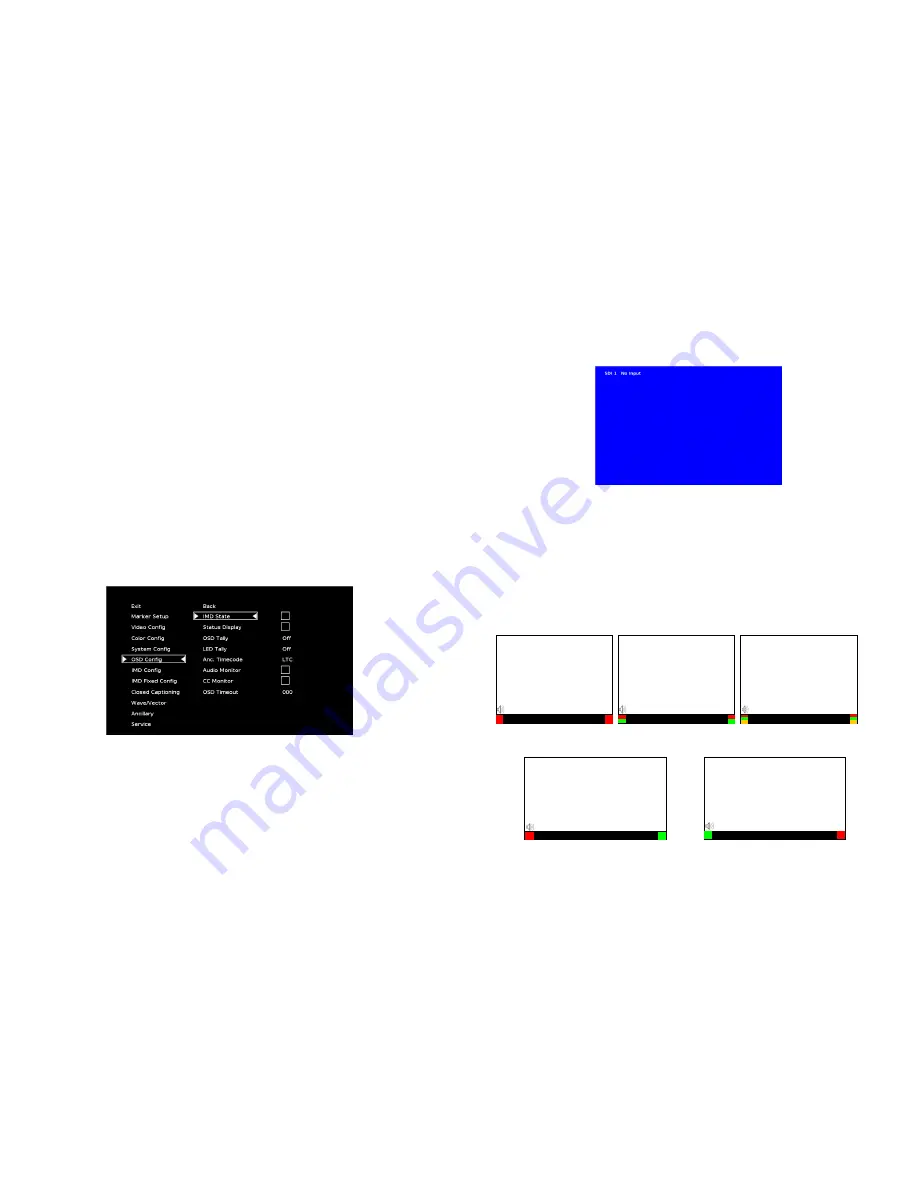
OSD Config Submenu
Use the OSD Configuration submenu to select a variety of information to be displayed on the screen.
■
IMD State
Use this setting to turn the IMD text display on or off. This setting affects both fixed string IMD text and remote IMD text
commands.
■
Status Display
OSD Configuration Submenu
19
Use this setting to enable or disable status display. When enabled, the current video input standard is displayed on the top
left of the screen. When disabled, status is only displayed for 2 seconds when the monitor is powered on, when an input is
applied, or when the input video standard changes. The status display reads “No Input” when no video input is present.
■
OSD Tally
Use this setting to choose how tally is displayed on the screen. The available OSD Tally options depend on the Tally Source
selected in the IMD Configuration submenu
When the Tally Source is set to Standard (contact closure), OSD Tally can be set to
Off
,
RGY
,
RG
, or
GR
:
• Off
On-screen tally is disabled
• RGY
Red, yellow, or green tally signals are indicated at both the bottom left and bottom right corners of the screen.
Two or three colors are shown simultaneously by subdividing each tally indicator
• RG
Red tally is shown at the bottom left of the screen, and green is shown at the bottom right.
• GR
Green tally is shown at the bottom left of the screen, and red is shown at the bottom right.
The following diagrams show RGY, RG, and GR OSD Tally modes:
Status Display
IMD Text
00:00:00:00
RG Mode: both colors activated
(red)
(red)
IMD Text
00:00:00:00
GR Mode: both colors activated
(red)
(red)
IMD Text
00:00:00:
IMD Text
00:00:00:
(red)
(red)
IMD Text
00:00:00:
(red)
(green)
(yellow)
(red)
(green)
(yellow)
RGY mode: single color
activated
RGY mode: two colors
activated
RGY mode: three colors
activated
(red)
(gree
n)
(red)
(gree
n)
Содержание V-R185-DLW
Страница 4: ...4 33...
Страница 6: ...6 31 Dimensions...


