Marshall Electronics Orchid OR-434 Скачать руководство пользователя страница 8

■  

Save CH Preset To >

Use this menu to select which one of 8 memory locations where the user wants to store the current channel 

output assignments.

■  

CH Preset

Use this menu to Lock or Unlock the ability to save to the Ch Preset memory locations.  This helps to prevent 

accidental overwriting of stored presets.  When Locked, Ch Presets may still be recalled.

WAVEFORM SUBMENU

■  

Layout

Use this menu to choose from several available preset 

screen layouts.  There are two layouts. Choosing any of the 

preset layouts will override the settings in the Waveform, 

Size and Position menus.

■  

Waveform

Use this menu to turn the Waveform display On or Off 

when in the Normal mode.

■  

Size

Use this menu to choose the size of the Waveform display in Normal mode.  Choices are Small, Medium, and 

Large.

■  

Position

Use this menu to select the position you want the Waveform display to occupy on the screen when in the 

Normal mode.  Choices are Left Top, Left Bottom, Right Top, and Right Bottom.

■  

Display Type

Use this menu to choose how to display the waveform. The choices are Overlay or Overlap.  In the Overlay 

mode, the waveform will be semi-transparent and the user will be able to see the source video through the 

waveform.  In the Overlap mode, the waveform will be Opaque and will block the source video.

■  

Y Over Limit

Use this menu to set where you want the waveform to display Red when the video source exceeds the limit set.  

This value is adjustable from -7.3% to 109.1% IRE.  This setting is shared with the ClipGuide Menu.

■  

Y Under Limit

Use this menu to set where you want the waveform to display Red when the video source below the limit set.  

This value is adjustable from -7.3% to 109.1% IRE.  This setting is shared with the ClipGuide Menu.


Limits


•  Internally, Y values ranges from 0 to 255


•  -7.3 IRE is equal to 0 in digital


•  0 IRE is equal to 16 in digital


•  100 IRE is equal to 235 in digital


•  109.1 IRE is equal to 255 in digital

17

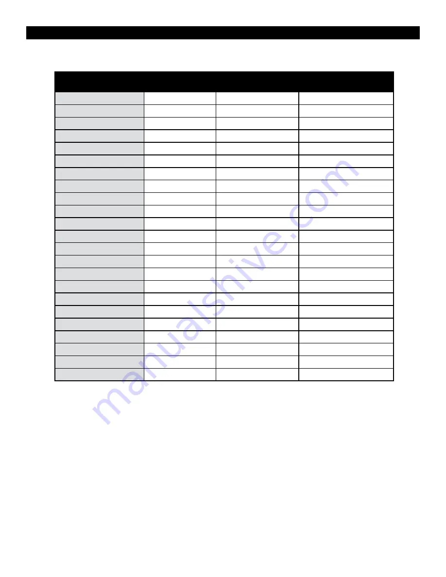
OR-434 Compatible Formats

8

Format 

HD/SD-SDI

Optional DVI 

Module

Optional Component 

Module  

480 / 60i 

ü


ü


576 / 50i 

ü


ü


480 / 60p   


ü

576 / 50p    

ü

720 / 60p      

ü

720 / 50p      

ü

720 / 30p      

ü

720 / 25       

ü

720 / 24p       

ü

1080 / 60p        

1080 / 50p        

1080 / 60i  (30PsF)   

ü

ü

ü

1080 / 50i  (25PsF) 

ü

ü

ü

1080 / 48i  (24Psf)

ü

ü

ü

1080 / 30p      

ü

1080 / 25p     

ü

1080 / 24p      

ü

VGA

ü

ü

SVGA  

ü

ü

XGA  

ü

ü

SXGA  

ü

ü

UXGA   

ü

ü

WUXGA        

Содержание Orchid OR-434

Страница 1: ...OR 434 Quad 4 3 Fully Featured Rack Mount Monitor System Operating Instructions Marshall Electronics...

Страница 2: ...n 14 Aspect Ratio Setting 14 Mono Color 14 H V Delay 14 Shift H 14 Shift V 15 MARKER CONFIGURATION SUBMENU 15 Markers 15 Center Marker 15 Aspect Markers 15 Safety Marker 15 Marker Mat 15 Line Thicknes...

Страница 3: ...ts and lighting conditions Real time Color Vectorscope The built in Vectorscope allows users to monitor color gamut range in real time It displays in full color and can also be displayed in various si...

Страница 4: ...rshall AR AM series is the perfect companion for monitoring audio Precision Audio Level Meters De embeds and displays up to 16 channels of audio using sixteen 64 segment tri color Audio Meters with us...

Страница 5: ...ntinental United States call 1 310 333 0606 Mounting The OR 434 monitor features a standard 19 rack mount configuration with tilt capability First secure the upper screws and then the lower ones as il...

Страница 6: ...ently move the Joystick Up Down Left or Right to navigate the on screen menu and to change values Press the Joystick IN to save any changes or selections Exit the on screen menu by moving the Joystick...

Страница 7: ...ast 1 Amp at 12 Volts IMPORTANT If using a power source other than the included power supply be sure that the polarity of the DC input is correct Pin 1 GND Pin 2 N C Pin 3 N C Pin 4 12VDC Option Slot...

Страница 8: ...SDI Optional DVI Module Optional Component Module 480 60i 576 50i 480 60p 576 50p 720 60p 720 50p 720 30p 720 25 720 24p 1080 60p 1080 50p 1080 60i 30PsF 1080 50i 25PsF 1080 48i 24Psf 1080 30p 1080 2...

Страница 9: ...5 CAL D93 RED BIAS 128 to 127 0 is Calibrated Setting GREEN BIAS 128 to 127 0 is Calibrated Setting BLUE BIAS 128 to 127 0 is Calibrated Setting RED GAIN 0 000 to 1 992 x1 00 is Calibrated setting GRE...

Страница 10: ...MALL MEDIUM LARGE POSITION LEFT TOP LEFT BOTTOM RIGHT TO RIGHT BOTTOM TYPE OVERLAY OVERLAP Y OVER LIMIT 100 0 IRE 0 to 109 1 Y UNDER LIMIT 100 0 IRE 7 3 to 109 1 VECTORSCOPE RETURN LAYOUT NORMAL LAYOU...

Страница 11: ...E REMOTE RETURN PIN 1 THRU 8 Pin 5 is Ground INPUT 1 INPUT 2 GAMMA 1 0 GAMMA 1 8 GAMMA 2 0 GAMMA 2 2 GAMMA 2 4 GAMMA 2 6 WHITEBLANCE D65 WHITEBALANCE D93 MONO SCAN ASPECT ZOOM HV DELAY RED ONLY BLUE O...

Страница 12: ...items by gently moving the Joystick control in the and positions Choose a submenu or select a menu item by pushing the Joystick control Return to the previous menu by pressing moving the Joystick in...

Страница 13: ...ts D65 6500K Conforms to CIE D65 White Point x 0 3127 y 0 3290 D93 9300K Conforms to Japanese D93 White Point x 0 2830 y 0 2980 USER Adjustable Color Bias and Gain CAL D65 D93 CAL D65 CAL D93 RGB Bias...

Страница 14: ...mainder of the screen regardless of its original format In 16 9 mode images are scaled to fill the maximum 16 9 portion of the screen 800 x 480 regardless of its original format Mono Color Use the Mon...

Страница 15: ...gs to superimpose one of 6 markers on the screen when in 16 9 mode 4 3 16 9 1 85 1 2 35 1 4 3 and 1 85 1 4 3 and 2 35 1 Safety Marker Use this setting to adjust the safety marker from 80 to 100 Off in...

Страница 16: ...the point at which the level meters will change color from Green to Yellow This is normally the level used for alignment For digital audio in the US the SMPTE standard is 20dBFS 0VU 4dBu The European...

Страница 17: ...ay to occupy on the screen when in the Normal mode Choices are Left Top Left Bottom Right Top and Right Bottom Display Type Use this menu to choose how to display the waveform The choices are Overlay...

Страница 18: ...will be Opaque and will block the source video Gain Use this menu to change the gain of the Vectorscope display Normally the Vectorscope displays x1 00 In order to allow a magnified view the gain is...

Страница 19: ...OR 434 Each of these F keys key may be assigned any one of 31 different functions as required by the job or individual user These functions are listed in the Menu Overview section of this manual One w...

Страница 20: ...Mix Red and Green for Amber Cannot mix R G B for White It will be pink due to white balance Cannot be assigned with separated tallies Left Right Separated Mode Supports R G B tallies on each Left and...

Страница 21: ...or accessing the menu Reset to MFG Default This will Restore all configuration values and functions to the factory preset state This will not change Model Name Serial Number or White Balance Data Requ...

Страница 22: ...ating Temperature 32 F to 104 F 0 C to 40 C Storage Temperature 4 F to104 F 20 C to 40 C RoHs Do not dispose Return to Manufacturer or Authorized Recycle Facility PANEL VIDEO INPUT OUTPUT HD SD SDI Vi...

Страница 23: ...aning and polishing practice Color Calibration Procedure Allow both the unit you want to calibrate and the Minolta CA 210 to warm up for a minimum of 20 minutes Attach the CA 210 color probe to the up...

Страница 24: ...ons or modifications in design or construction void this warranty It is considered normal for a minimal amount of pixels not to exceed three to fail on the periphery of the display active viewing area...

Отзывы: