


Rear Panel Features
Parallel Remote RJ-45
Pin Assignments
Pin 1
GPI 1
Pin 2
GPI 2
Pin 3
GPI 3
Pin 4
GPI 4
Pin 5
GND
Pin 6
GPI 5
Pin 7
GPI 6
Pin 8
GPI 7
GPI Input
RJ-45 connector for 7 user-assignable GPI inputs. Assignable using the on-screen menu.
Service Port
Proprietary connection used for firmware upgrades and LCD color balance calibration.
Power Input
Connect 12VDC to the 4-Pin XLR power input connector. Power can be supplied from the included power
supply or from a variety of DC sources supplying at least 1 Amp at 12 Volts.
IMPORTANT: If using a power source other than the included power supply, be sure that the polarity of
the DC input is correct:
Pin 1: GND
Pin 2: N/C
Pin 3: N/C
Pin 4: +12VDC
Option Slot
Used to connect an optional input card such as the OR-DVI (DVI input) or OR-YPR (Component input).
Audio Output
3.5mm stereo line level output for monitoring embedded audio channels. The desired audio channels are
selected in the Audio onscreen menu. The output level is also controlled through the Audio onscreen menu.
Video input and output connectors
The video input auto detects HD and SD-SDI video signals.
The output connector is an active re-clocked video signal from the HD/SDI input.
1
2
3
4
6
5
1
5
4
6
2
3
7
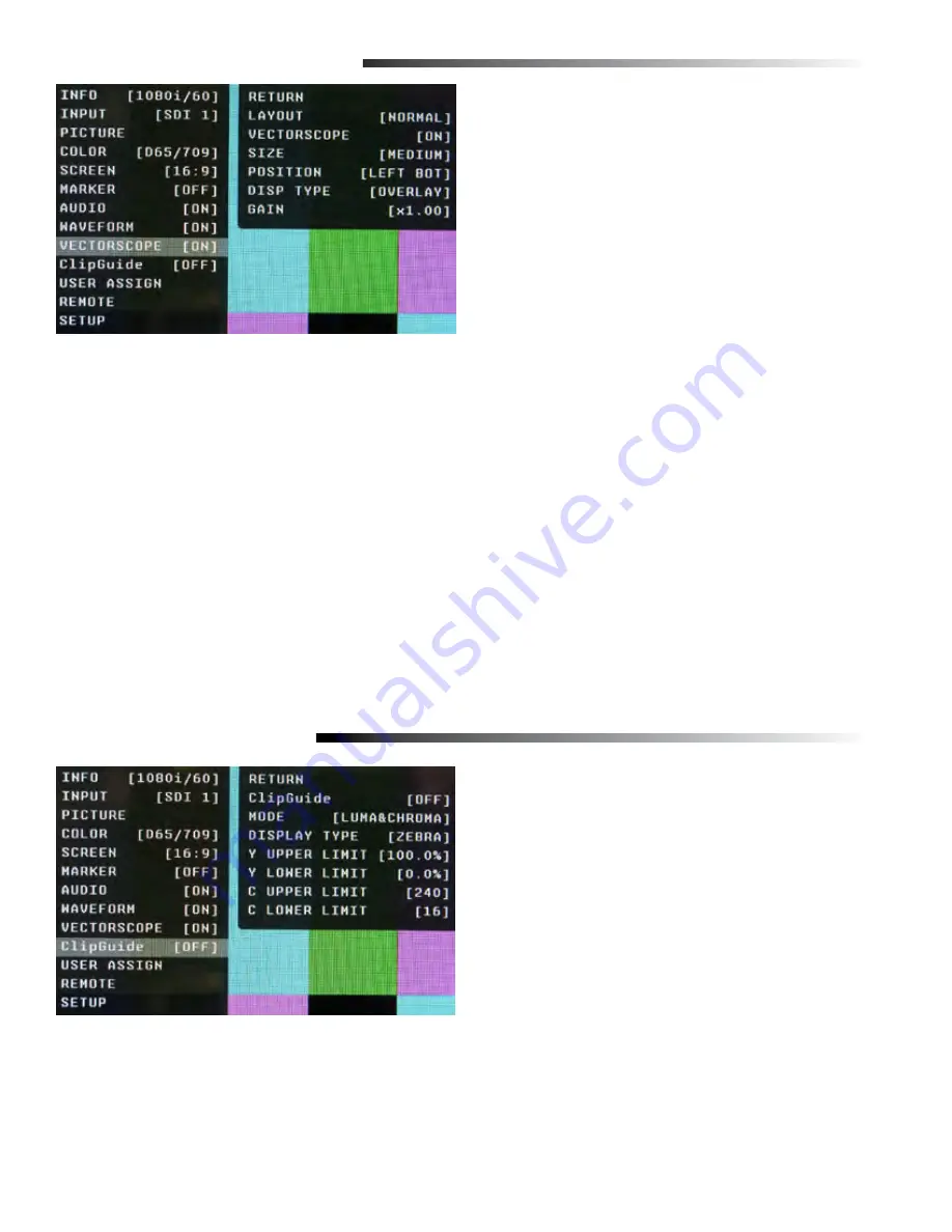
VECTORSCOPE SUBMENU
■
Layout
Use this menu to choose from several available preset
screen layouts. There are two layouts. Choosing any
of the preset layouts will override the settings in the
Vectorscope, Size, and Position menus.
■
Vectorscope
Use this menu to turn the Vectorscope display On or Off when in the Normal mode.
■
Size
Use this menu to choose the size of the Vectorscope display in Normal mode. Choices are Small, Medium,
and Large.
■
Position
Use this menu to select the position you want the Vectorscope display to occupy on the screen when in the
Normal mode. Choices are Left Top, Left Bottom, Right Top, and Right Bottom.
■
Display Type
Use this menu to choose how to display the Vectorscope. The choices are Overlay or Overlap. In the Overlay
mode, the Vectorscope will be semi-transparent and the user will be able to see the source video through the
Vectorscope. In the Overlap mode, the Vectorscope will be Opaque and will block the source video.
■
Gain
Use this menu to change the gain of the Vectorscope display. Normally, the Vectorscope displays x1.00. In
order to allow a magnified view, the gain is adjustable from x1.00 to x4.98 in .01 steps. Changing this value has
no effect on the source material.
ClipGuide SUBMENU
■
ClipGuide
Use this menu to turn the ClipGuide function On or Off.
■
Mode
Allows the choice of which ClipGuide function you want
to display. There are 6 modes to choose from:
• Luma (Y) displayed over Color video
• Luma (Y) displayed over Mono video
• Chroma (C) displayed over Color video
• Chroma (C) displayed over Mono video
• Luma (Y) and Chroma (C) displayed over Color Video
• Luma (Y) and Chroma (C) displayed over Mono Video
18
■
Display Type
ClipGuide will display over and under values in two ways when monitoring the video signal. In the Zebra
mode, over and under conditions are indicated in a Zebra (diagonal stripe) pattern. In the Fill mode, over and
under conditions are indicated by a solid fill. In either Zebra or Fill mode, Red is the indication for Luma and
Yellow is the indication for Chroma.


