


On-Screen Menu
OR-434 MENU STRUCTURE OVERVIEW
INFO [1080i / 60]
MODEL NAME
OR-434
OPTION CARD
N/A
OPTION S/N
INPUT
SDI
INPUT FORMAT
1080i / 60
COLOR MATRIX
709
COLOR TEMP
D65
VERSION
0.0.0.0
INPUT [SDI]
RETURN
INPUT SELECT
[SDI] / OPTION
Analog Calibrate
>
PICTURE
RETURN
BRIGHT
0~100 [50] is Calibrated setting
CONTRAST
0~100 [50] is Calibrated setting
SATURATION
0~100 [50] is Calibrated setting
SHARPNESS
0~100 [0] is Calibrated setting
GAMMA
1.0/1.8/2.0/2.2/2.4/2.6 [2.2] is Calibrated Setting
COLOR [D65 / 709]
RETURN
COLOR MATRIX
AUTO, RGB, BT. 601, BT. 709
COLOR TEMP
CIE D65, JP D93, USER, CAL D65/D93, CAL D65, CAL D93
RED BIAS
-128 to 127 [0] is Calibrated Setting
GREEN BIAS
-128 to 127 [0] is Calibrated Setting
BLUE BIAS
-128 to 127 [0] is Calibrated Setting
RED GAIN
0.000 to 1.992 [x1.00] is Calibrated setting
GREEN GAIN
0.000 to 1.992 [x1.00] is Calibrated setting
BLUE GAIN
0.000 to 1.992 [x1.00] is Calibrated setting
SCREEN [16 : 9]
RETURN
SCAN
NORMAL, OVERSCAN, ZOOM
ASPECT
AUTO, 4:3, 16:9
MONO COLOR SEL
RGB
MONO
RED
GREEN
BLUE
R+G
R+B
G+B
H/V DELAY
ON / OFF
SHIFT H
-128 to 127 [0] is Calibrated Setting (- = Right)
SHIFT V
-128 to 127 [0] is Calibrated Setting (- = Down)
MARKER
RETURN
MARKER
ON / OFF
CENTER
ON / OFF
ASPECT RATIO
OFF
4:03
16 : 9
1.85 : 1
2.35 : 1
4 : 3 & 2.85 : 1
4 : 3 & 2.35 : 1
SAFETY ZONE
80% to 100% (OFF) [95%] is normal setting
MARKER MAT
CLEAR, HALFTONE, BLACK
LINE THICKNESS
1, 2, 3
LINE LEVEL
GRAY, HALFTONE, WHITE, INVERT
9
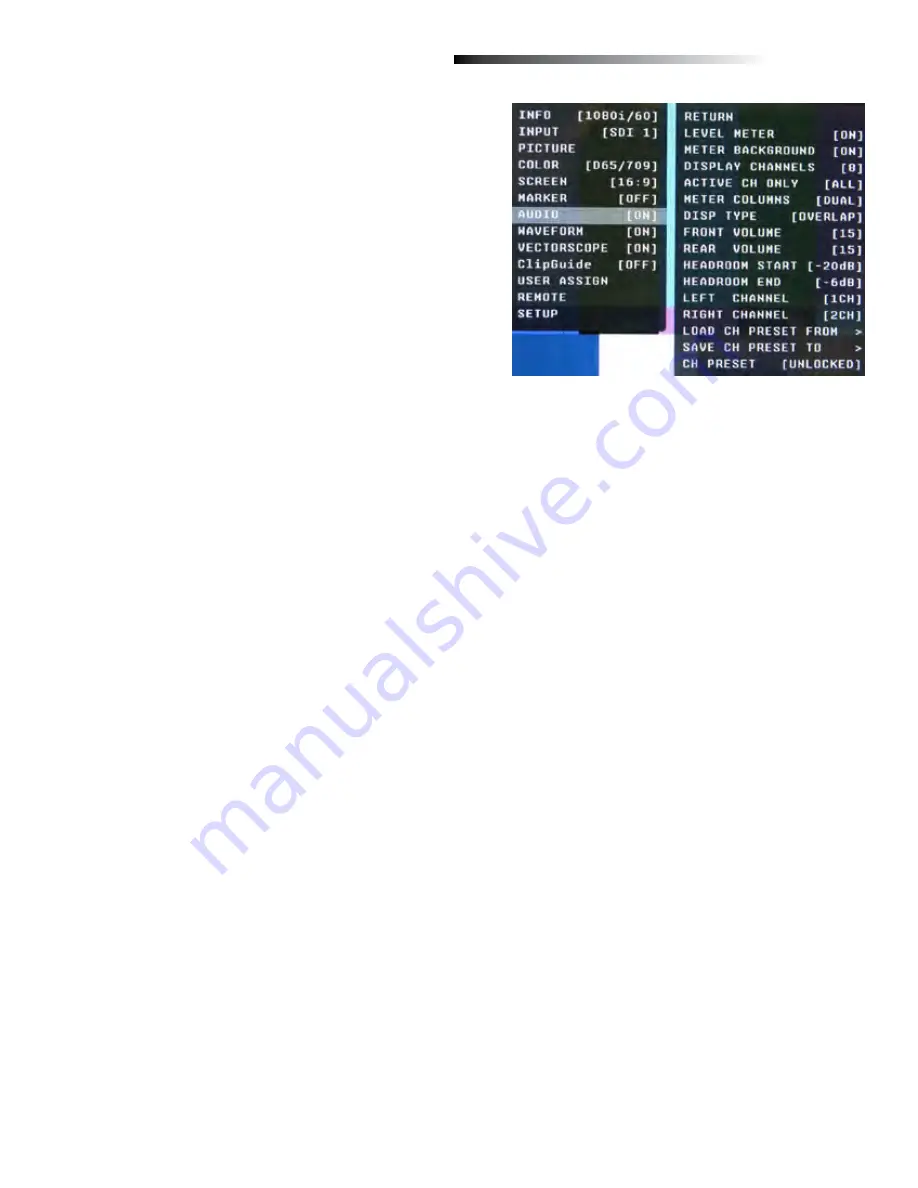
■
Level Meter
Selects whether or not to display audio level meters.
■
Meter Background
Selects whether or not to display meter background.
■
Display Channels
Selects how many audio meters you want to display.
You may select any number of channels from 1 to 16.
■
Active Channel Only
Allows a choice of All channels or Active channels only.
Selecting Active will override the Display Channels setting.
■
Meter Columns
Allows a choice of displaying Level Meters is Dual (2) or Quad (4) columns.
■
Display Type
Allows a choice between Overlap and Overlay modes. Overlap is opaque and will block part of the video
image where the Level Meters appear. Overlay is Halftone (semi-transparent) so video can be seen through the
Level Meters.
■
Front Volume
Adjusts Headphone volume on the front panel. This value is adjustable from 0 to 40. Setting to 0 will Mute the
output.
■
Rear Volume
Adjusts the Line Output jack on the rear panel. This value is adjustable from 0 to 40. Setting to 0 will Mute the
output.
■
Headroom Start
Adjusts the point at which the level meters will change color from Green to Yellow. This is normally the level
used for alignment. For digital audio in the US, the SMPTE standard is -20dBFS = 0VU = +4dBu.
The European EBU standard is -18dBFS = 0VU. Other Alignment standards can be set using this menu.
■
Headroom End
Adjusts the point at which the level meters will change color from Yellow to Red. There is no official standard
to where this point should occur. This is an arbitrary setting to give visual warning that the program level is
peaking near the 0dBFS point at which there are no more bits and clipping will occur.
■
Left Channel / Right Channel
These menus are used to designate which one of the available 16 audio channels will be assigned to either the
Left, Right, or both outputs for listening. For example, the user can choose to send CH 1 to the left output and
CH 2 to the Right output, or the user can assign CH 1 to both Left and Right for a mono feed.
■
Load CH Preset From >
Use this menu to recall one of the 8 possible memory locations where the user previously stored channel output
assignments. Use of this Load command will override the current channel output assignments.
AUDIO CONFIGURATION SUBMENU
16


