26
Network
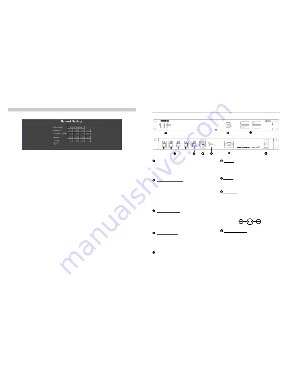
The Network Settings page is shown below:
o
MAC Address –Indicates the MAC Address of your NCB-2010. This cannot be changed.
o
IP Address – This field shows the current IP Address of the NCB-2010. You can change this by typing the
desired IP address in the text field and pressing Set below the Gateway field. You will be prompted to begin a
new instance of the NCB-2010 Web Interface with the new IP Address. Please consult your IT department for
information on valid IP address ranges on your network before you change this.
o
Broadcast Address – This field shows the current Broadcast Address of the NCB-2010. You can change this by
typing the desired Broadcast address in the text field and pressing Set below the Gateway field. Please consult
your IT department for information on valid Broadcast addresses ranges on your network before you change this.
o
Netmask – This field shows the current Netmask used by the NCB-2010. You can change this by typing the
desired Netmask in the text field and pressing Set below the Netmask field. Please consult your IT department
for information on selecting an appropriate Netmask.
o
Gateway – This field shows the current Gateway used by the NCB-2010. You can change this by typing the
desired Gateway in the text field and pressing Set below the Gateway field. Please consult your IT department
for information on selecting an appropriate Gateway.
7
Front and Rear Panel Features
POWER LED and Rocker Switch
The POWER LED indicates whether the NCB-2010
is in the ON or OFF state. The rocker switch
controls the power state of the NCB-2010. The
rocker switch is protected in order to avoid
accidental tripping of the switch.
RX – TX – READY LEDs
The Wall / Host RX and TX LEDs indicate whether
data is being received (RX) or transmitted (TX) by
the NCB-2010. The Wall RX / TX LEDs indicate that
information is being received and transmitted to IMD
equipped monitors. The Host RX LED indicates that
the NCB-2010 is receiving and transmitting
information. During the boot process, the READY
LED will remain lit. When the NCB-2010 is ready to
operate, the READY LED will blink.
RS-485 / 422 Port 1-4
The RS-485 / 422 ports send MEI protocol
commands to Marshall’s IMD line of monitors. Up to
128 screens can be connected to each port. These
ports also pass Image Video or TSL v3.1/v4.0
protocol commands from the RS-485 / 422 Port 5,
embedded in the MEI protocol.
RS-485 / 422 Port 5
The RS-485 / 422 port 5 is a Control Input that
receives Image Video or TSL v3.1 or v4.0 protocol
commands from an external controller. These
commands are then embedded in MEI protocol and
sent to the IMD monitors.
USB Peripheral Port
Use the USB peripheral ports to connect a USB
Mouse and USB keyboard to the NCB-2010 system
while in Console / Debugging mode.
Ethernet
The Ethernet port is an RJ-45 network interface used
to connected the NCB-2010 to a standard TCP/IP
network. The NCB-2010 is operated via an
embedded web interface
Console
The Console port is used for debugging purposes.
Please contact Marshall Electronics for instructions
on how to use this port.
Power Input
Connect the 12VDC input to the 2-Pin twist lock
power input connector. Note that the NCB-2010 takes
about 3 minutes to start up after power on, before the
unit is functional.
IMPORTANT: If using a power source other than the
included power supply, be sure that the polarity of
the DC input is correct:
USB Peripheral Ports
Use the USB peripheral ports to connect a USB
Mouse and USB keyboard to the NCB-2010 system
while in Console / Debugging mode. This is also a
bootable USB port when used with a USB Memory
Stick containing NCB-2010 Firmware.
READY


