39
40
14. DSP
14. DSP
14. DSP
14. DSP
14. DSP の説明
の説明
の説明
の説明
の説明
DSP56004によるデジタル処理は以下2ブロック構成になっていま
す。
1.DSP1(Q507)
●ミュート機能(コサインカーブによる 32‑Sample 約 0.7mS)。
● ‑12dB アッテネーション機能(CD‑7 使用せず)。
●ディエンファシス機能(44k/48k)。
● DC‑Filter 機能。ON/OFF 可能(CD‑7 では固定)。
●信号フォーマット(IIS‑IN/OUT)。
2.DSP2(Q509)
●デジタルフィルター機能(FIR による 4fs、3Type‑mode)。
●ノイズシェーパー機能(first order)及びラウンド。
● Output‑DATA のオフセット機能。
●信号フォーマット(IIS‑IN/OUT)。
DSP の動作説明
DSP56004(Q507/Q509)は電源 ON にした時、リセット状態から立ち
上がる際に ROM(Q506/Q508)のデータをロードします。
この間約0.5secでディフォルトのパラメーターの設定を全て完了
します。
完了すると各DSPはそれぞれのパラメーターによるデジタル処理
を開始します。
電源 ON にした時はイニシャルで CD‑ モードの Filter‑1 が設定さ
れます。
操作ボタンによるFilterとノイズシェーパーの変更及びサンプリ
ング周波数の切り換えの場合に限り、新たなパラメーターによる
デジタル処理に切り変わります。
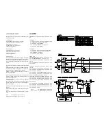
これらのパラメーターの変更はROM‑1とROM‑2の真理表(Table 1)
によって決定されます。真理表からわかるように、それぞれの機
能は DSP‑1 と DSP‑2 によって、個別に動作します。
また、DSPが動作してるかどうかは、DSPの入出力ピンに信号が出
ていることで確認できます。パラメーターの更新がされてそれぞ
れのモードに設定されたかどうかは、パラメーターの更新シーケ
ンスのタイムチャート(Figure 2)のインパルス信号の特性によっ
て確認をします。
ミュートとディエンファシスのON/OFFではパラメーターの再設定
は行いません。これらの切り換えは DSP(Q507)の端子を直接コン
トロールしています。従って、Pin をコントロールする事により
下記の状態を確認できます。
ミュート
:Pin 73(Q507)=High でオン、Low でオフ。
ディエンファシス :Pin 74(Q507)=High でオン、Low でオフ。
14. EXPLANATION OF DSP
The digital processing for DSP-1/DSP-2 (DSP56004) is the
following compositions.
1. DSP-1 (Q507)
Mute (32-Sample<cosine curve> approx. 0.7mS)
-12dB attenuation (It is not available for CD-7)
De-emphasis (44k / 48k mode)
DC-Filter ON/OFF (It is fixed for CD-7)
Signal format (IIS-IN/OUT)
2. DSP-2 (Q509)
Digital filter (4fs<FIR>, 3Type-mode)
Noise shaper (first order) and Round
Offset of Output-DATA
Signal format (IIS-IN/OUT)
Procedure of DSP
The DSP56004 (Q507/Q509) loads data of ROM (Q506/Q508)
at that moment of the product is POWER ON. The all param-
eters of default setting will be done approx. 0.5 seconds. And
then, each DSP device starts digital processing by each pa-
rameter.
The product is set in Filter-1 of CD-mode initially when POWER
ON.
When the filter and the noise shaper is shifted and the sam-
pling frequency is shifted to other frequency except 44.1kHz,
Those parameters are changed to other parameters.
REMARK : The change of the sampling frequency depend on
the input of digital signal.
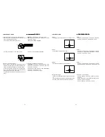
These changes of parameters are based on the function tables
of ROM-1 and ROM-2 (Figure 1). Each function of DSP-1 and
DSP-2 actuates individually.
If signals are confirmed at the input or output pins of DSP, that
is actuated for DSP.
The setting confirmation of each mode after the parameter
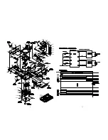
updated, which will be able to refer to the impulse signals of
timing chart (Figure 2).
When mute or de-emphasis is switched, the parameters is not
changed.
Because these switches control the pins of DSP devise (Q507)
directly.
Then, the following status are confirmed by the pin control
status.
Mute
Pin 73(Q507) : High = on, Low = off
De-emphasis Pin 74(Q507) : High = on, Low = off
Figure 1
Table 1
44kHz
48kHz
44.1kHz
48kHz
44.1kHz
44.1kHz
48kHz
48kHz
Содержание 74 CD7
Страница 8: ...7 8 6 WIRING DIAGRAM ...
Страница 10: ...9 SCHEMATIC DIAGRAM AND PARTS LOCATION 11 12 ...
Страница 11: ...13 14 ...
Страница 12: ...15 16 ...
Страница 13: ...17 18 ...
Страница 14: ...19 20 ...


