Designed in Italy Assembled in China
Center Frequency, Band Width (Q) and Gain can be adjusted.
“Center Frequency”: the selectable frequencies range is from 20Hz to 20kHz in
steps of 1/24 of an Octave.
“Q factor”: the selectable Q range is from 0.5 up to 10 in steps of 0.1 Q.
“Gain”: the selectable Gain range is from -12dB to +6dB in steps of 0.5 dB.
Center Frequency, Band Width (Q) (Slope) and Gain can be adjusted.
“Center Frequency”: the selectable frequencies range is from 20Hz to 20kHz in
steps of 1/24 of an Octave.
“Q factor (Slope)”: the selectable Q range is from 0.5 up to 3 in steps of 0.1Q
“Gain”: the selectable Gain range is from -12dB to +6dB in steps of 0.5 dB.
Center Frequency, Band Width (Q) (Slope) and Gain can be adjusted.
“Center Frequency”: the selectable frequencies range is from 20Hz to 20kHz in
steps of 1/24 of an Octave.
“Q factor (Slope)”: the selectable Q range is from 0.5 up to 10 in steps of 0.1Q.
“Gain”: the selectable Gain range is from -12dB to +6dB in steps of 0.5 dB.
BELL filter
Variable Q Low Shelving Filter:
Variable Q High Shelving Filter:
Note: each single filter can be independently “bypassed” for an easy setting/use of them.
To “Bypass” the single filter, just press the “Bypass” button beneath the filter’s parameters.
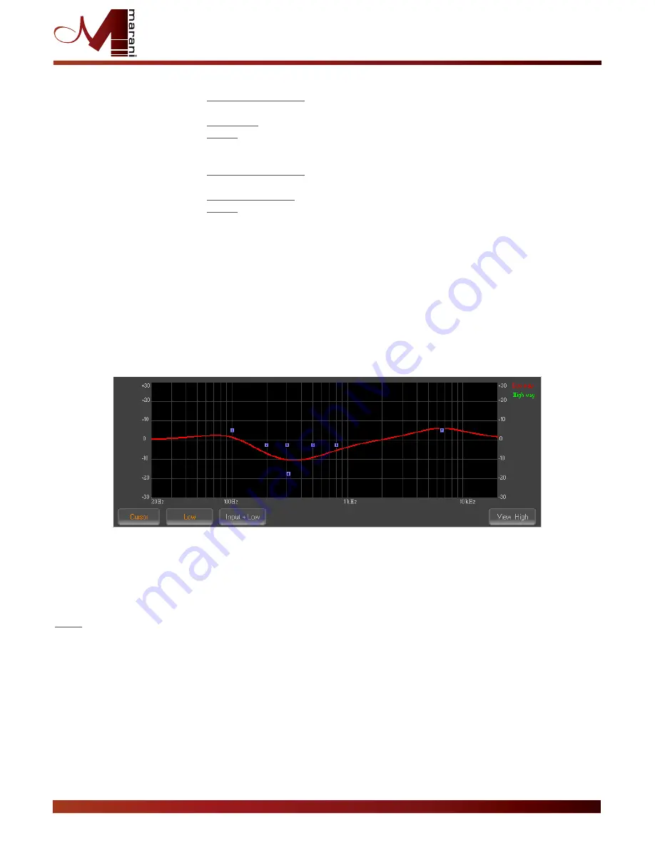
The set up of the filters and specially their frequency placement can also be done with the use of the mouse,
just activating the “Cursor” function, pressing the related button on the left bottom of the frequency
response Graphic.
Once the all 7 available cursor are shown on the Frequency Response graphic, just selecting anyone of them
with the mouse's arrow and maintaining the mouse's click pressed, it is possible to move and place the
selected cursor on the desired frequency and with the desired gain.
For setting the filter's Q, still need to enter the desired value directly in the dedicated box in the filters' editing
frame.
Note: in the Eq graphic can be shown in the same time the filtering set up of the currently edited Low Out
page, just pressing the LOW button.
To the Low Output filter setting, in the graphic can be superposed also the set up of the other Signal path
pages as the Input Filter setting, just pressing the INPUT+LOW button, or even the VIEW HIGH in order to
visualize on the graphic the overall filter setting of the all Signal paths.
PDA500P User Manual


