4
DO unplug the receiver from the mains, TV, and the satellite LNB feed when a thunderstorm is expected.
DO unplug the receiver from mains out let before cleaning the unit.
CONNECTIONS AND CONTROLS
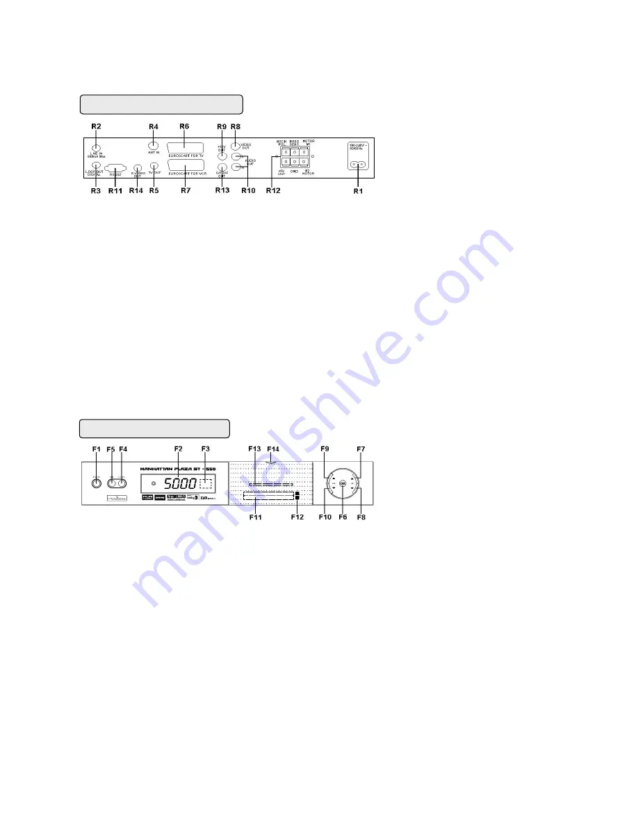
CONNECTORS AND DEFINITIONS
Please do not connect the power to the receiver until all other connections have been made and checked.
R1: AC IN (Power Cord) Connect this lead to the mains outlet (100-240 V AC 50/60 Hz)
R2: LNB IN ( IF Input ) Connect the IF cable from your LNB to this connector.
R3: LOOP OUT If you have a second satellite receiver, connect the receivers LNB input to this connector.
R4: ANT IN Connect your UHF TV antenna to this connector.
R5: TV OUT (UHF Modulator Output) Connect your TV or VCR to this connector.
R6: EUROSCART FOR TV Connect your TV via a SCART cable to this connector.
R7: EUROSCART FOR VCR Connect your VCR or DVD Player via a SCART cable to this connector.
R8: VIDEO Composite video output for connecting to an AV monitor etc.
R9: 0/12V Sw 12V DC output for use with LNB switches.
R10: AUDIO LEFT / RIGHT Audio outputs for connecting to a Hi-Fi system.
R11:
RS-232 Connect your PC to this connector using a NULL MODEM (female to female) cable for software
upgrade. Connect STB for channel data transfer from another receiver of same model.
R12: M1, M2, MECH POL, REED SENS, GND, + 5V M1 and M2 connectors for the DC motor, REED SENS and GND
connectors for REED switch on your positioner. MECH POL, GND and +5V connectors for a Mechanical Polarizer.
R13: SP / DIF Digital audio output for connecting to a HiFi system
R14: S- VIDEO Additional video output for connecting to a VCR or CAMCORDER with S-VIDEO capability
FRONT PANEL CONNECTORS
CONTROLS AND DEFINITIONS
F1: STANDBY / ON After connecting the power, press this button to switch ON the receiver or to switch to STANDBY
F2: DIGIT LED DISPLAY This will display the channel number or certain programming functions when using the menus.
In standby mode it will display the time.
F3: REMOTE CONTROL SENSOR Location of the infrared receiver. Do not obstruct this when using the remote control.
F4: TV / RADIO Press this button to change from TV channels to RADIO channels and vise versa.
F5: MENU Press this button to enter the programming menus. To exit the menus, press it again.
F6: OK In viewing mode press this button to display channel list. In menu mode this button is used to enter the
programming parameters.
F7: CH UP In viewing mode it will step up channels sequentially. In programming mode it will move the cursor upwards
in the menu.
F8: CH DOWN In viewing mode it will step down channels sequentially. In programming mode it will move the cursor
downwards in the menu.
F9: VOL UP In viewing mode it will increase the sound. In programming mode it will move the cursor to the
right or change a function.
F10: VOL DOWN In viewing mode it will decrease the sound. In programming mode it will move the cursor to
the left or change a function.
F11: COMMON INTERFACE (CI) SLOTS A AND B Your receiver is equipped with two slots (behind the front flap)
accepting Type 1 and Type 2 PCMCIA modules. Open flap from top catch (F14) and Insert CI module together with smart
card into either of these slots.
F12: CI SLOTS A AND B EJECT When you want to remove a cam press the eject button.
F13: IRDETO CARD SLOT (For Models with embedded Irdeto) Insert your smart card into this slot.
BACK PANEL CONNECTIONS
FRONT PANEL CONTROLS


