background image

5

1

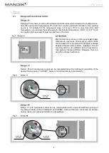
Damper

2

Mounting plate

3

Sealing cover

4

Seal plates

5

Mounting plate cover

6

Thermal fuse

7

Mechanics

8

Actuator

9

Temperature sensor

10 Sensor sticker

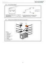
1(COM) - black wire
2(NC) - 

gray wire

4(NO) - 

blue wire

This limit switch is possible to connect in following two versions:

a) 

 if the arm is moving … connect wire 1+2

b) 

 if the arm is moving … connect wire 1+4

AC 230V / 5A

IP 67

-25°C … +120°C

Содержание FDMQ

Страница 1: ......

Страница 2: ...nd effective area 19 5 Placement and Assembly 27 6 Statement of installations 29 7 Thin shaft wall 60 8 Installation frames 63 9 Suspension system 71 10 Pressure loss 77 11 Coefficient of local pressu...

Страница 3: ...racteristics CE certified acc to EN 15650 Tested in accordance with EN 1366 2 Classified acc to EN 13501 3 A1 Fire resistance EIS 120 EIS 90 External Casing leakage class C Internal leakage class 2 ac...

Страница 4: ...nce is only in size of inner spring which closes the fire damper For the size of fire dampers is always assigned the size of mechanism It is not recommended to use different size of mechanism than giv...

Страница 5: ...fuse 7 Mechanics 8 Actuator 9 Temperature sensor 10 Sensor sticker 1 COM black wire 2 NC gray wire 4 NO blue wire This limit switch is possible to connect in following two versions a if the arm is mo...

Страница 6: ...the back spring displaces the damper blade into the breakdown position CLOSED The time of displacing the blade from the position OPEN to the position CLOSED takes maximum 20 sec In case that the powe...

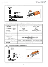
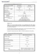
Страница 7: ...s 20 s Ambient temperature normal duty safety duty non operating temperature 30 C 55 C The safe position will be attained up to max 75 C 40 C 55 C Connecting motor auxiliary switch cable 1 m 2 x 0 75...

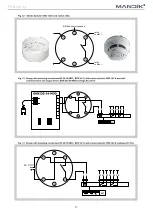
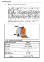
Страница 8: ...complemented with smoke detector ORS 142 K The voltage can be AC 230 V or 24 V DC Design with voltage AC 230 V is equpped with Communication and supply device BKN 230 24 MOD and with actuating mechan...

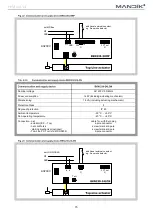
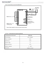
Страница 9: ...9 2 3 4 5 6 1 relay contact relay contact RS Bus communication 1 2 3 4 5 6 7 1 2 S2 S1 S3 S5 S4 S6 2 3 4 5 6 1 BAT Tf Tf LED 1 2 S2 S1 S3 S5 S4 S6 24 V DC 2 3 4 5 6 1 BAT Tf Tf LED...

Страница 10: ...drive on one hand and on the other hand it transmits the signal informing about the flap valve position OPERATION and FAILURE through 2 conductor wiring to the central Control command SWITCHED ON SWI...

Страница 11: ...h spring return Protection Class II Degree of protection IP 40 Ambient temperature Non operating temperature 20 C 50 C 40 C 80 C Connection net motor terminal board cable 0 9 m with EURO plug type 26...

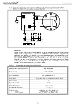
Страница 12: ...0 24 MOD can be installed separately without a connection to a master control system in which case the connection bridge between the terminals 1 and 4 must be installed For more information see the Be...

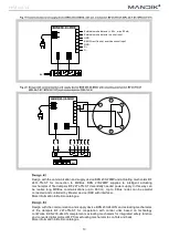
Страница 13: ...nformation in Belimo catalogue Design with the communication and supply device BKN 230 24LON and actuating mechanisms of fire dampers BF 24TL TN ST for cooperation with control units based on technolo...

Страница 14: ...and BKN 230 24MP cable 1 m 4 x 0 75 mm halogen free Nominal voltage AC 230 V 50 60Hz Power consumption 11 W including actuator mechanism Dimensioning 13 VA including actuator mechanism Protection Clas...

Страница 15: ...50 C 40 C 80 C Connection net actuator BF Top net LonWorks starting mechanism optional Top Line PC Tool via ZIP RS232 cable 1m with Euro plug 4 pole connector screw terminal 2 pole screw terminal 2 p...

Страница 16: ...tacts are available Contacts showing operating and failure position of the damper are active when the damper is in the given position Function check can be done by pressing and holding the button RESE...

Страница 17: ...tor wiring and issues control commands Proper damper operation is indicated by two light LED diodes Control ON position OPERATION Control OFF position FAILURE If the fire damper do not reach the given...

Страница 18: ...18 Nominal voltage AC 24 V 50 60Hz Power consumption 3 5 W Dimensioning 5 5 VA Protection Class III Degree of protection IP 30 Ambient temperature 0 50 C Connection terminal 2 x 1 5 mm...

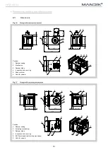
Страница 19: ...sing 2 Mechanics 3 Damper blade 4 Inspection hole covering 5 Sensor sticker 6 Hole for camera 35 A 10 B 10 275 35 80 20 65 A 30 375 B 30 Position 1 Damper casing 2 Actuating mechanism 3 Damper blade 4...

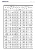
Страница 20: ...53 298 22 0 23 5 0 1370 BFN M2 123 14 0 15 5 0 0519 BFL M1 78 323 23 0 24 5 0 1470 BFN M2 148 15 0 16 5 0 0597 BFL M1 10 0 10 1 0 0191 BFL M1 173 16 0 17 5 0 0674 BFL M2 13 10 5 12 0 0 0259 BFL M1 198...

Страница 21: ...0 21 0 0 1059 BFL M1 13 13 5 15 5 0 0431 BFL M1 173 19 5 22 5 0 1196 BFL M2 23 14 0 15 5 0 0506 BFL M1 198 20 5 23 5 0 1334 BFN M2 36 14 5 16 5 0 0600 BFL M1 203 21 0 24 0 0 1361 BFN M2 48 15 0 17 0 0...

Страница 22: ...351 BFN M2 48 19 0 22 0 0 1064 BFL M1 223 28 5 31 5 0 2541 BFN M2 63 20 0 23 0 0 1236 BFL M1 238 29 5 32 5 0 2684 BFN M2 73 21 0 24 0 0 1351 BFL M1 3 248 30 0 33 0 0 2779 BF M2 80 5 21 5 24 5 0 1438 B...

Страница 23: ...0 0 3656 BF M2 80 5 25 0 28 0 0 1813 BFL M2 28 273 40 0 43 0 0 3969 BF M2 100 5 26 5 29 5 0 2103 BFN M2 33 278 40 5 43 5 0 4031 BF M2 123 28 5 31 5 0 2429 BFN M2 53 298 42 0 45 0 0 4281 BF M3 148 30 5...

Страница 24: ...0 52 0 0 5994 BF M3 198 50 5 53 5 0 5941 BF M3 78 323 51 5 54 5 0 6431 BF M4 203 51 5 54 5 0 6064 BF M3 23 1 23 2 0 0829 BFL M1 223 54 0 57 0 0 6554 BF M3 13 26 0 27 5 0 1121 BFL M1 238 55 5 58 5 0 6...

Страница 25: ...729 BFN M2 223 62 5 65 5 0 7891 BF M4 63 44 0 45 5 0 3171 BFN M2 238 64 0 67 0 0 8334 BF M5 73 45 5 48 5 0 3466 BFN M2 3 248 65 5 68 5 0 8629 BF M5 80 5 46 5 49 5 0 3688 BFN M2 28 273 69 5 72 5 0 9366...

Страница 26: ...ctuating mechanism Tab 4 2 1 the weight of BKN 0 5 kg Dampers can be supplied on the customer s demands in all subdimension of the above mentioned range Flanges of rectangular fire dampers are 30 mm w...

Страница 27: ...y space for access to the control device all other items must be situated at least 350 mm from the control parts of the damper At least one inspection hole must be accessible The damper must be instal...

Страница 28: ...ion with fire classification EI120 or EI 90 The fire damper can also be integrated outside the wall construction Duct and the damper part between the wall construction and the damper blade labelled wi...

Страница 29: ...S 90 42 100 Stuffing box with fire protection mastic and cement lime plate EIS 90 43 100 Installation frame E1 E3 E4 EIS 90 44 100 Weichschott Ablative Coated Batt EIS 90 45 100 Battery installation f...

Страница 30: ...Duct 75 100 Around the perimeter 20 75 100 Used materials example 3 HILTI CFS F FX EIS 60 PROMAFOAM C EIS 45 SOUDAL Soudafoam FR B1 EIS 30 DenBraven Fire protection foam EIS 30 Position 1 Fire damper...

Страница 31: ...r or gypsum Installation opening for each damper has minimal dimensions a x b A 100 x 2xB 100 mm or 2xA 100 x B 100 mm Gap between damper and construction is filled by mortar or gypsum Distance betwee...

Страница 32: ...ty 140 kg m 75 75 75 50 A 100 B 100 Gap between damper and construction is filled by mortar or gypsum and mineral wool Wool is fixed to damper body and construction by fire protection mastic Mineral w...

Страница 33: ...et Position 1 Fire damper 2 Solid wall construction 3 Stuffing box mineral stone wool min density 140 kg m 4 Fire protection mastic min thickness 1 mm 5 Cement lime plate min thickness 15 mm min densi...

Страница 34: ...34 100 100 100 Position 1 Fire damper 2 Installation frame 3 Solid wall construction...

Страница 35: ...800 max 2050 D 60 to 800 max 1650 Position 1 Fire damper 2 Solid wall construction 3 Fire resistant board 4 Fire stop coating thickness 1 mm 5 Duct Used materials example 3 Hilti CFS CT B 1S 140 50 4...

Страница 36: ...m x B 85 3 mm or a x b A 85 3 mm x 2x B 85 3 mm 20 mm Gap between frame and damper body and frame and construction must be filled by glue PROMAT K84 Distance between dampers 104 mm Flange to flange co...

Страница 37: ...per from the structure is not limited Insulation materials can be replaced by another approved fire sealing system with equivalent properties The maximum distance of the fire damper from the structure...

Страница 38: ...ted and according to EN 15882 2 must use the required number of hinges according to EN 13366 1 2014 For installation methods outside a construction when the damper size is A 800 mm it is necessary to...

Страница 39: ...39 Position 1 Fire damper 2 Installation frame E6 3 Solid wall construction 4 Cement lime plate 5 Duct 100 75 Around the perimeter...

Страница 40: ...Position 1 Fire damper 2 Gypsum plate 3 Mineral wool type depending on the type of construction 4 Fire protection foam 5 Stucco plaster 6 Duct 75 Around the perimeter Installation opening has to be re...

Страница 41: ...y fire protection mastic Installation opening for each damper has minimal dimensions a x b A 100 x 2xB 100 mm or 2xA 100 x B 100 mm Gap between damper and construction is filled by mortar or gypsum Di...

Страница 42: ...illed by mortar or gypsum and mineral wool Wool is fixed to damper body and construction by fire protection mastic Mineral wool thickness construction thickness 20 mm or 50 mm Installation is valid fo...

Страница 43: ...sity 870 kg m 7 Duct Used materials example 4 Promapyr Rockwool Steprock HD Hilti CFS CT B 1S 140 50 5 Promastop P K Hilti CFS CT 6 Promatect H 75 20 100 300 25 Screw min 4x50 300 25 300 Around the pe...

Страница 44: ...ofile is fixed by screws 3 5 mm with corre sponding length Distance between screws 200 mm Installation opening has to be reinforced by steel U profile Profile is fixed by screws 3 5 mm with corre spon...

Страница 45: ...t board 5 Fire stop coating thickness 1 mm 6 Duct Used materials example 3 Hilti CFS CT B 1S 140 50 4 Hilti CFS CT 100 D 60 to 800 max 2050 D 60 to 800 max 1650 Installation opening has to be reinforc...

Страница 46: ...umber of holes and screws Installation opening dimensions a x b 2x A 85 3 mm 20 mm x B 85 3 mm or a x b A 85 3 mm x 2x B 85 3 mm 20 mm Gap between frame and damper body and frame and construction must...

Страница 47: ...47 Position 1 Fire damper 2 Installation frame 3 Solid ceiling construction 4 Wall with possibility of ceiling movement min 110 Concrete min 125 Aerated concrete...

Страница 48: ...00 Installation opening has to be reinforced by steel U profile Profile is fixed by screws 3 5 mm with corre sponding length Distance between screws 200 mm 75 20 80 100 Installation opening has to be...

Страница 49: ...ol 9 Duct 100 variable 300 25 Screw min 4x50 300 25 300 100 400 60 120 75 20 Stuffing box fire protection mastic cement lime plate and insulation materials can be replaced by another approved fire sea...

Страница 50: ...50 Position 1 Fire damper 2 Solid ceiling construction 3 Mortar or gypsum 4 Duct Around the perimeter 75 min 110 Concrete min 125 Aerated concrete...

Страница 51: ...dampers can be filled by mineral stone wool min density 140 kg m3 Wool is fixed to damper body by fire protection mastic Installation opening for each damper has minimal dimensions a x b A 100 x 2xB...

Страница 52: ...onstruction 3 Stuffing box mineral stone wool min density 140 kg m 4 Fire protection mastic min thickness 1 mm 5 Cement lime plate min thickness 15 mm min density 870 kg m 6 Duct Screws has to be fixe...

Страница 53: ...53 min 110 Concrete min 125 Aerated concrete Position 1 Fire damper 2 Installation frame 3 Solid ceiling construction...

Страница 54: ...ceiling construction 3 Fire resistant board 4 Fire stop coating thickness 1 mm 5 Duct min 110 Concrete min 125 Aerated concrete Used materials example 3 Hilti CFS CT B 1S 140 50 4 Hilti CFS CT D 60 to...

Страница 55: ...2 2 800 A1 1200 3 3 1200 A1 1600 4 4 1600 A1 2000 5 5 2000 A1 2400 6 6 2400 A1 2800 7 7 2800 A1 3000 8 8 Installation opening dimensions a x b 2x A 85 3 mm 20 mm x B 85 3 mm or a x b A 85 3 mm x 2x B...

Страница 56: ...y another approved fire sealing system for damper installation with equivalent material properties Depends on the distance of the flap from the construction when the maximum distance from the construc...

Страница 57: ...Duct Position 1 Fire damper 2 Solid ceiling construction 3 Installation frame E4 4 Concrete B20 5 Rebar 6 Duct 750 30 100 75 30 100 75 750 100 100 Around the perimeter min 110 Concrete min 125 Aerated...

Страница 58: ...58 75 Position 1 Fire damper 2 Installation frame E6 3 Solid ceiling construction 4 Cement lime plate 5 Duct Around the perimeter min 110 Concrete min 125 Aerated concrete...

Страница 59: ...ilti CFS CT B 1S 140 50 4 Promastop P K Hilti CFS CT 5 HILTI CFS S ACR Position 1 Fire damper 2 Sandwich wall construction 3 Stuffing box mineral stone wool min density 140 kg m 4 Fire protection coat...

Страница 60: ...200mm to the support structure The boards are mounted to tight butt joints without need of cementing The second sheathing layer is screwed to the first sheathing layer using screws Rodurit in square n...

Страница 61: ...ple 3 Glasroc F Ridurit th 20 mm 4 Steel U profile 50 5 Screw Ridurit 6 Glasroc F Ridurit th 20 mm 100 250 50 250 50 50 20 20 110 75 It is alternatively possible to use Knauf or Promat solution Instal...

Страница 62: ...rew Ridurit 6 Glasroc F Ridurit th 20 mm 7 Promaseal XT Dimensions Number ZB1 Number ZH1 A B 400 1 1 400 A B 800 2 2 800 B 1200 3 3 1200 B 1500 4 4 100 250 50 250 50 20 20 80 It is alternatively possi...

Страница 63: ...63 E1 Cement lime 100 150 100 E2 Galvanized plate 100 150 E3 Cement lime 100 E4 Cement lime 100 150 Solid ceiling construction 150 100 150 E5 Cement lime 100 E6 Cement lime 100 150...

Страница 64: ...ped by intumescent sealing It enlarges its capacity and air proofs the gap between damper body and installation frame and between installation frame and wall construction Gypsum wall construction has...

Страница 65: ...wall construction Solid ceiling construction Damper is on the body equipped by intumescent sealing It enlarges its capacity and air proofs the gap between damper body and steel cartridge Gypsum wall...

Страница 66: ...de is cement lime cartridge equipped by intumescent sealing It enlarges its capacity and air proofs the gap between cement lime cartridge and construction Gypsum wall construction has to be installed...

Страница 67: ...uctions with concrete On the inside is installation frame equipped by intumescent sealing It enlarges its capacity and air proofs the gap between installation frame and damper body Gypsum wall constru...

Страница 68: ...gypsum wall construction with ceiling movement possibility Distance of movement x On the inside and outside is installation frame equipped by intumescent sealing It enlarges its capacity and air proo...

Страница 69: ...40 mm min density 450 kg m All parts are glued with glue Promat K84 and secured by screws Dampers has to be suspended in an appropriate manner see chapter 9 Screw min 4x80 Installation frame E6 is sui...

Страница 70: ...nd damper placement outside wall construction is necessary to use reinforcement VRM Q 1 Cut the groove for profil U25x40x25 2 Insert profile into groove 3 Fix profile 4 Fix second layer of insulation...

Страница 71: ...234 M20 245 150 300 Position 1 Threaded rod M8 M20 2 Nut 3 Washer 4 Coupling Nut 5 Anchor 6 Hinge plate min thickness 10 mm 7 Concrete screw tested for fire resistance R30 R90 max Tension up to 0 75...

Страница 72: ...to the wall recommended type 8 Nut M8 with anchor 9 Screw with hexagon head 10 Installation hols 11 Screw M6x10 Nut M6 12 Gypsum grid from C profile Assembly and mounting shown on the picture are ill...

Страница 73: ...to the wall recommended type 6 Nut M8 with anchor 7 Installation hols 8 Screw M6x10 Nut M6 A Assembly and mounting shown on the picture are illustrative and serve as a guide The method of attachment m...

Страница 74: ...orted so as all load transfer from the back to back piping to the damper is absolutely excluded On Fig 83 is typical mounting situation as an example Threaded rods longer than 1 5 m require fire resis...

Страница 75: ...nting profiles Load the suspension system depend on weight of the fire damper Damper can be suspended from the ceiling construction or supported above the ceiling construction Damper assembly procedur...

Страница 76: ...n systems is 1500 mm Damper assembly procedures must be done so as all load transfer from the fire separating constructions to the damper body is absolutely excluded Back to back air conditioning pipi...

Страница 77: ...n p w 2 p Pa presure loss w m s air flow speed in nominal damper section kg m air density coefficient of local pressure loss for the nominal damper section see Tab 11 1 1 Determination of pressure los...

Страница 78: ...0 312 0 300 0 278 0 263 0 252 0 239 0 231 0 223 0 216 0 213 0 209 0 335 0 311 0 301 0 289 0 274 0 257 0 244 0 233 0 223 0 215 0 209 0 205 0 203 1 644 1 628 1 622 1 609 1 605 1 591 1 580 1 551 1 535 1...

Страница 79: ...72 6 74 3 75 7 78 0 79 7 83 4 85 1 57 4 60 6 62 8 64 6 66 0 67 2 68 2 69 1 70 0 73 1 75 3 77 1 78 5 80 7 82 5 86 1 87 9 59 9 63 1 65 3 67 1 68 5 69 7 70 7 71 6 72 4 75 6 77 8 79 6 81 0 83 2 85 0 88 6...

Страница 80: ...6 7 24 1 33 2 43 9 4 0 4 1 5 9 9 4 14 6 21 5 30 40 3 4 2 3 9 5 3 8 4 13 1 19 5 27 6 37 4 4 5 3 9 4 9 7 5 11 9 17 9 25 7 35 1 4 9 3 9 4 5 6 9 10 9 16 7 24 1 33 2 5 2 3 9 4 3 6 4 10 1 15 6 22 7 31 5 5 5...

Страница 81: ...mper body lower sheet of mechanics lock holder 1 lock lever 2 lock spring 8 dia stopper pin mechanics pin 5 Inspection hole cover including the clip and fasteners if they are parts of the cover 6 Bear...

Страница 82: ...method of reception is specified in the purchase order the handover of the dampers to the forwarder shall be understood as reception The dampers must be stored in covered buildings in an environment...

Страница 83: ...the blade must be protected from dust fibrous or adhesive masses and solvents Actuator control without electric voltage A special lever part of the actuator may be used to manually set the dampers to...

Страница 84: ...on Fire Equipment by Authorized persons The author ized persons can be trained by Producer or by authorized Distributor All effective safety standards and directives must be observed during fire dampe...

Страница 85: ...ent function checks the following checks must be carried out for dampers with optical smoke detector The function checks of the optical smoke detector are to be carried out by employees of an authoriz...

Страница 86: ...V 50 With actuating mechanism BF 24 TN BFL BFN 24 T with smoke detector ORS 142 K voltage AC DC 24 V 51 With communication and supply device BKN 230 24 and actuating mechanism BF 24 TN ST BFL BFN 24...

Страница 87: ...see www mandik com MAND K a s Dob sk 550 26724 Hostomice Czech Republic Tel 420 311 706 706 E Mail mandik mandik cz www mandik com WEIGHT kg Dob sk 550 267 24 Hostomice Czech Republic MAND K a s ACTUA...

Отзывы: