10
TPM 092/13
4.1.
Dimensions
Fig. 14 Fire damper FDMD, design .01 - damper with inner mechanical control
Fig. 15 Fire damper FDMD, design .01v1 -
damper with outer
mechanical control
Position:
1
Damper casing
2
Damper blade
3
Control lever
4
Shutting spring
5
Base plate
6
Lever lock “OPEN”
7
Starting mechanism
8
Lever lock “CLOSED”
9
Thermal protective fuse
10
Inspection hole covering
11
Limit switch “CLOSED”
12
Limit switch “OPEN”
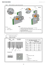
Fig. 16 Fire damper FDMD, design .01v2 - damper with outer mechanical control and mechanical control cover
Position:
1
Damper casing
2
Damper blade
6
Lever lock “OPEN”
7
Starting mechanism
8
Lever lock “CLOSED”
9
Thermal protective fuse
10
Inspection hole covering
13
Mechanical control cover
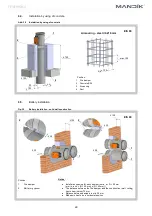
4. Dimensions, weights
Position:
1
Damper casing
2
Damper blade
3
Shutting spring
4
Thermal protective fuse
5
Inspection hole covering
6
Limit switch


