


P
7
/ 2
3
[3] DISASSEMBLY/ASSEMBLY
[3] -2. Tool Holder Section (cont.)
R
epair
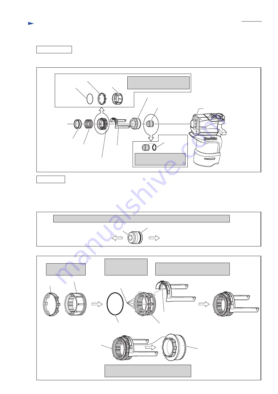
DISASSEMBLY
ASSEMBLY
Ring 38
O ring 53 and Lock sleeve are
removed from Driving sleeve.
Driving sleeve section
Striker
Cylinder 34
Straight bevel gear 35
Compression
spring 39
Link arm
O ring 27
Replace the old O ring 27
in this step.
O ring 53
Lock sleeve
Lock sleeve
Driving sleeve
Fig. 18
3) Parts assembled to Cylinder 34 are removed. (
Fig. 18
)
1) Pay attention to the descriptions in
Figs. 19 and 20
.
2) Insert Striker into Cylinder 34. And to Crank housing, assemble Straight bevel gear 35, the Driving sleeve section
with Link arm, Compression spring 39 and Ring 38. Refer to
Fig. 18
.
Fig. 19
Fig. 20
O ring 27
Bulge portion
Crank housing side
Impact bolt side
Rib on Link arm
Mount Lock sleeve
on Driving sleeve.
Fit O ring 53 into the
grooves on Driving
sleeve.
Fit the rib of Link arm into the groove
on Driving sleeve.
Facing O ring 27 installation side of Striker to Crank housing, insert Striker into Cylinder 34.
Groove on Driving sleeve
Straight bevel gear 35
(assembled in Crank
housing complete)
Grooves for O ring 53
O ring 53
Driving sleeve
Fix Driving sleeve to Crank housing
while engaging with Straight bevel gear 35.
Driving sleeve


