background image

P  

7

/ 1

8

R

epair

[4] DISASSEMBLY/ASSEMBLY

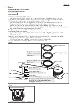
[4]-5. Trimmer head ass’y (cont.)

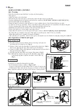
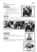
(7) Remove M8x8 Hex socket head bolt from Gear housing 

      complete, and insert 1R236 into the threaded hole, then 

      press down 1R236 to remove the assembled part of 

      Spiral bevel gear 12 and two Ball bearings 6000ZZ from 

      Gear housing complete. (

Fig. 18

)

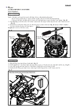
(8) Remove two M4x16 Hex socket head bolts, and then pull 

      out Angular plate from Gear housing complete.

      The following parts can be removed together with 

      Angular plate. (

Fig. 19

)


• Retaining ring S-10


• Spiral bevel gear 22

       • Ball bearing 6001ZZ (2 pcs.)

       • Spiral bevel gear 11 


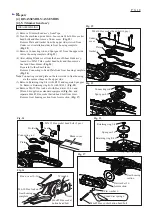
(9) Remove Retaining ring S-10 from the groove of Spiral

      bevel gear 11 to disassemble the parts around Angular 

      plate.

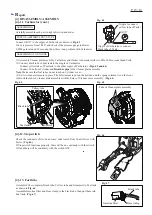
(10) Disassemble Slide lever set by unscrewing two 4x18 

        Tapping screws. (

Fig. 20

)

(11) Remove M5x25 Hex socket head bolt and two Stop 

        rings E-4 (

Fig. 21

) then separate Cover from 

        Pipe holder/ Joint. (

Fig. 22

)

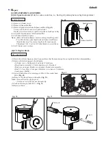
(12) Loosen four M4x20 Hex socket head bolts and then 

        remove Pipe holder. (

Fig. 23

)

(13) Remove two M4x16 Hex socket head bolts, (

Fig. 24

)

        and then press down Spindle complete in Pipe holder 

        with 1R247. (

Fig. 25

)


Fig. 20

Fig. 21

Fig. 22

Fig. 23

Fig. 24

Fig. 25

Fig. 18

Fig. 19

Spiral bevel gear 12

Spiral bevel

gear 22

M4x16 Hex socket head bolt (2 pcs.)

Gear housing

complete

Gear housing

complete

Angular plate

Joint

Joint

Cover

4x18 Tapping screw (2 pcs.)

Slider lever set

M5x25 Hex socket

head bolt

Stop ring E-4 (2 pcs.)

Ball bearing 

6000ZZ (2 pcs.)

Ball bearing 6001ZZ

(2 pcs.)

Spiral bevel gear 11

M8x8 Hex socket

head bolt

1R236

Rod 5

(2 pcs.)

Pipe

holder

Pipe holder

M4x16

Hex 

socket 

head bolt

(2 pcs.)

Cover

Spindle complete

1R247

M4x20 Hex 

socket head 

bolt (4 pcs.)

Содержание EN4950H

Страница 1: ...ries only Note The standard equipment for the tool shown above may vary by country Hedge trimmer head set Shear blade assembly with End cover Shear blade assembly without End cover End cover set for s...

Страница 2: ...emoving Ball bearing 6000DDU from Cutter shaft complete Bearing setting plate 10 2 1R033 removing Ball bearings Gear extractor Large 1R045 Air density tester 1R127 diagnosing Carburetor Drill chuck ex...

Страница 3: ...tect parts and product from unusual abrasion Fig 1 Once Engine is disassembled remove oil grease from the mating surface of Cylinder and Crankcase complete then apply ThreeBond 1215 to the mating surf...

Страница 4: ...5x12 Hex socket head bolt Fig 4 Fig 6 Fig 7 Fig 5 Fig 3 Connector 4pcs Adjust screw Projection of Insulator Swivel Nuts Nuts to fix on the projection of Insulator Water pump pliers Rag Follow the inst...

Страница 5: ...socket head bolt with flat washer and spring washer and M5x25 Hex socket head bolt and then separate Trimmer head ass y from Shaft and Pipe complete manually or using Waterpump pliers and Plastic ham...

Страница 6: ...the lower side in Gear housing are the same as those on the upper side 5 Remove Retaining ring S 8 with 1R291 and separate Spur gear 24 Remove Retaining ring R 26 with 1R291 Fig 15 6 Remove M6 10 Hex...

Страница 7: ...ever set by unscrewing two 4x18 Tapping screws Fig 20 11 Remove M5x25 Hex socket head bolt and two Stop rings E 4 Fig 21 then separate Cover from Pipe holder Joint Fig 22 12 Loosen four M4x20 Hex sock...

Страница 8: ...13mm width groove of 1R139 and put them on 1R217 so that Cam A comes to the hole Then press down the shaft end of Spiral bevel gear 9 with 1R280 Fig 29 Fig 26 Fig 28 Pipe holder Holder plate Shaft en...

Страница 9: ...ex socket button head bolt Fig 32 After adjusting the tightening torque of M6x85 Hex socket button head bolt so that Joint and Gear housing can be set to the desired angle without any backlash secure...

Страница 10: ...se section 3 Remove Clutch drum from Clutch case section with 1R247 and Arbor press Fig 38 1 Put Clutch case on the table of Arbor press vertically then pressfit Clutch drum into Ball bearing 6201LLU...

Страница 11: ...plug carefully 4 Install Plug cap with Plug cap spring on Plug and connect the plug screw part to a metal part of Engine then pull Starter rope slowly The sparks can be seen when starter rope is pull...

Страница 12: ...hen screw two M6 bolts into Flywheel as drawn in Fig 46 instead of M6x25 shoulder hex bolts Flywheel is removed from Engine Important Screw two M6 bolts evenly ASSEMBLING 1 Wipe off the grease and oil...

Страница 13: ...52 how to make a knot of the rope 4 Wind the rope two or three turns around Reel 5 While turning Reel counterclockwise fit it into Starter case and hook Spiral spring end on the rib inside of Starter...

Страница 14: ...op of Inlet needle is not deformed worn out Fig 61 5 When Control lever is set in place make sure that Spring is put properly as drawn in Fig 62 6 Regarding three M3x8 Pan head screws with washers loo...

Страница 15: ...er elements in place The felt element is put on the bottom and the sponge element is on the front 4 Hook the tabs of Cleaner plate assembly with the holes of Cleaner cover assembly Fig 64 Check the co...

Страница 16: ...ds to screw them 6 Set Cylinder cover in place 1 Drain the oil from Engine as much as possible so that the remaining oil is not spilled out when disassembling 2 Remove the following parts from Engine...

Страница 17: ...eak Do not enlarge them too much when fixed 4 Assemble Cylinder block assembly Degrease the matching surface of Cylinder block and Crank case Refer to Fig 73 apply ThreeBond 1215 on the Crank case sid...

Страница 18: ...ad bolt M5 16 Flange nut M8 Hex socket head bolt M4 20 W SW MEC Hex socket head bolt M5 16 Nut M5 Hex socket head bolt M5 16 Clutch bolt M6 25 Hex socket head bolt M5 40 W MEC M10 P1 0 Hex socket head...

Отзывы: