


P 8/ 29
R
epair
[3] -1. Motor section
ASSEMBLING
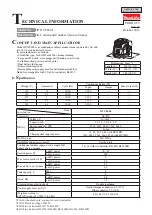
1. Set the machine, Separator (34) top,
Float cage (48) down.
Fig. 6
(34)
(65)
(48)
(39)
(9)
2. Put the Lead wires of Motor assembly (39)
on this route.
3. Connect the lead wires of motor assembly (39
)
with those of Controller C (65).
4. Set Top damper (9) to the reverse side
of Cowling complete (7),
* aligning its notch to the center of
Cowling complete (7)
* aligning its shape to that of Cowling
complete.
(9)
(7)
(3) Connect Motor assembly’s lead wires with Controller C and stick Top damper to the reverse side of Cowling complete.
Fig. 6
.