manualshive.com logo in svg
background image


7

18

R

epair

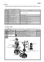
[3] DISASSEMBLY/ASSEMBLY

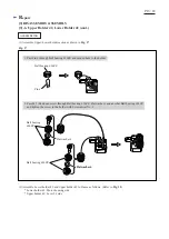
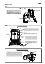
[3] -3. Gear housing
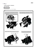
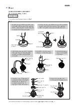
Fig. 8

DISASSEMBLING

Lock washer

Spur gear 14 

(3 pcs.)

Gear housing 

cover

1. Remove Gear housing

    cover from Gear housing

    by unscrewing three 4x18

    Tapping screws.

2. Remove Lock washer, Spur gear 14

    (6 pcs.), Spur gear 7 complete and

    Internal gear 36 from Gear housing.

3. Remove Retaining ring S-15

    from Spindle of Gear housing

    with 1R291.

4. Disassemble Spindle 

    with 1R045.

Gear 

housing

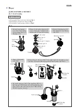
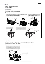
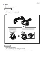
(1) Disassemble Motor section as drawn in 

Fig. 4

.

(2) Disassemble DC Motor as drawn in

 Fig. 5

.

(3) Disassemble Gear housing as drawn in 

Fig. 8

.

Spur gear 7 complete
Internal gear 36

Spindle

Spur gear 14 

(3 pcs.)

Retaining ring S-15

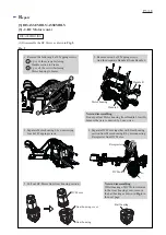
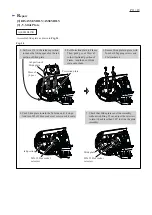
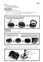
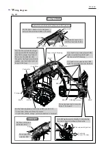
5. Remove Ring 15. Then, set M6x17 Hex socket head bolt to Spindle as a jig.

    And then, disassemble Ball bearing 6902ZZ from Spindle with 1R269. 

Ring 15

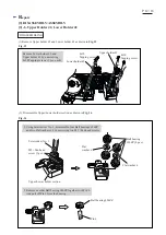
6. Put Gear housing on 1R232. Then, applying 1R248 to 

    Ball bearing 6902ZZ from Lock washer assembling side,

    press it down with Arbor press to remove Ball bearing

    6902ZZ from Gear housing.

Spindle

Spindle

 1R045

M6x17 Hex socket

head bolt

Ball bearing 

6902ZZ

Spindle

 1R269

Gear housing

1R232

Ball bearing 

6902ZZ

1R248

Содержание DPB181

Страница 1: ...arger DC18SD Charger DC24SC Automotive charger DC18SE Battery BL1815N Battery BL1820 Battery BL1830 Battery BL1840 Battery BL1850 Battery Variable speed control dial Blade speed m s ft min Type Voltag...

Страница 2: ...all bearings 1R291 Retaining ring S and R pliers removing assembling Retaining ring S 15 1R311 Retaining ring pliers with long bent nails removing assembling LED 2 LUBRICATION Apply Makita grease N No...

Страница 3: ...tion as drawn in Fig 2 Handle R 4x18 Tapping screw 7 pcs 1 Separate Handle R from Handle L by unscrewing seven 4x18 Tapping screws 2 Remove Switch and Switch lever from Handle L 3 Remove Lock off butt...

Страница 4: ...4 1 Push out the tap of Cap from the groove of Wheel A with a slotted screwdriver and then remove Cap as drawn below 2 Remove M6x17 Hex socket head bolt with Impact driver while holding the wheel by h...

Страница 5: ...r remains in the Gear housing cover remove the ball bearing as drawn in Fig 6 in the next page Handle R Handle L Note in disassembling Do not pull out Motor housing from Handle L forcibly because they...

Страница 6: ...and 4 Gear housing Motor housing R Motor housing L 4x18 Tapping screw 4 pcs Gear housing cover Ball bearing 1R232 1R283 Gear housing cover Gear housing cover Gear housing ASSEMBLING Gear housing cove...

Страница 7: ...ion as drawn in Fig 4 2 Disassemble DC Motor as drawn in Fig 5 3 Disassemble Gear housing as drawn in Fig 8 Spur gear 7 complete Internal gear 36 Spindle Spur gear 14 3 pcs Retaining ring S 15 5 Remov...

Страница 8: ...with Arbor press 5 Assemble Retaining ring S 15 to Spindle with 1R291 1R031 Spindle Gear housing Gear housing 2 Put Gear housing onto 1R036 and insert the assembled Spindle section into Gear housing...

Страница 9: ...holder by unscrewing four 4x18 Tapping screws 1 Disassemble Lever shaft as drawn in Fig 10 Lever holder Lever shaft Plane bearing 30 Compression sprig 9 4x18 Tapping screws 4 pcs 1 Set Compression spr...

Страница 10: ...n of Lever 54 Face the grip portion of Lever 54 to the release mark side and mount the lever to Lever shaft while aligning the lever to the guide line Release mark Tension mark 4 Assemble Lever holder...

Страница 11: ...without wobbling If not adjust the set screw to turn it back less than 180 to slide the plate smoothly 3 Secure Slide plate in place with four 4x18 Tapping screws and Flat washers 4 Sleeve 5 4 pcs M5x...

Страница 12: ...8 Tapping screws 2 pcs each Fig 15 Fig 16 4x18 Tapping screw 4x18 Tapping screw Lower holder 42 Upper holder 42 Pin 6 Ball bearing 696ZZ Ball bearing 696ZZ 4 pcs Flat washer 6 Flat washer 6 1 Using Sc...

Страница 13: ...696ZZ Flat washer 6 2 Pass M5 Pan head screw through Ball bearing 696ZZ Flat washer 6 and another Ball bearing 696ZZ and tighten the screw to the holder with Screwdriver No 3 Flat washer 6 Flat washe...

Страница 14: ...below 2 Fit the rest portion of Rubber tire to Wheel by pressing it by hand Note Make sure that Rubber tire fits to Wheel closely Insert small slotted screwdriver into the notch of Wheel then remove R...

Страница 15: ...Fig 5 2 Remove LED light circuit as drawn in Fig 21 1 Set LED Light circuit to Handle L Note Be careful that the circuit is not damaged when assembling 2 Insert Rubber pin 4 to the place as drawn in...

Страница 16: ...res sheath Black Orange to Switch to DC Motor to Terminal Line filter if used to Switch LED Line filter if used Fuse if used Controller unit Controller DC Motor Switch Terminal are connected to Contro...

Страница 17: ...nt line of Handle L s edge Joint line Lead wires red blue have to be put into Lead wire holders A and B Pass the Lead wires through Line filters Line filter Put one Line filter between Rib A and Lead...

Страница 18: ...the place as drawn below Switch Do not put Fuse onto this Rib Fix the above lead wires with this lead wire holder Pass Lead wires black orange connected to DC Motor through Line filter and put Line fi...

Отзывы: