P
3
/
18
R
epair
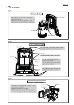
[3] DISASSEMBLY/ASSEMBLY
[3] -1. Switch section
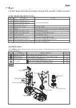
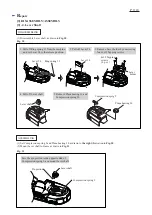
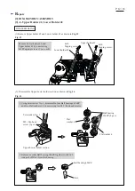
Fig. 2
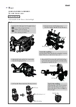
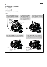
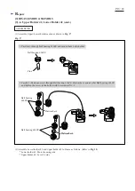
Fig. 3
DISASSEMBLING
ASSEMBLING
(1) Assemble Leaf spring and Lock off button to Handle L as drawn in
Fig. 3
.
(2) Assemble Switch section to Handle L by reversing the disassembly procedure. (
Fig. 2
)
1. Fit Leaf spring to Lock off button.
Disassemble Switch section as drawn in
Fig. 2
.
Handle R
4x18 Tapping screw
(7 pcs.)
1. Separate Handle R from Handle L by unscrewing
seven 4x18 Tapping screws.
2. Remove Switch and Switch lever from Handle L.
3. Remove Lock off button and Leaf spring from Handle L.
Note
: Be careful not to lose Leaf spring.
Handle L
Switch
Switch lever
2. Mount Lock off button together with Leaf spring to Handle L.
Note
: Be sure that Leaf spring is mounted exactly into
Handle L before mounting Handle R.
Lock off button
Leaf spring
Lock off button
Leaf spring

