


P
5
/
18
R
epair
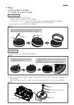
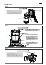
Fig. 5
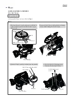
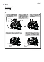
2. Remove seven 4x18 Tapping screws.
And then separate Handle R from Handle L.
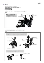
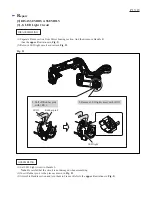
3. Separate Motor housing L by unscrewing
four 4x18 Tapping screws.
4. Separate DC Motor together with Gear housing
section from Motor housing R by disconnecting
Receptacles from DC Motor.
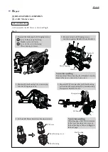
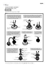
5. Pull out DC Motor from Gear housing section.
Note in disassembling
:
If Ball bearing of DC Motor remains
in the Gear housing cover, remove
the ball bearing as drawn in
Fig. 6
in
the next page.
Handle R
Handle L
Note in disassembling
:
Do not pull out Motor housing from Handle L forcibly
because they are connected by Lead wires.
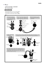
(2) Disassemble the DC Motor as drawn in
Fig. 5
.
Receptacles
Ball bearing
Motor housing
DC Motor
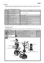
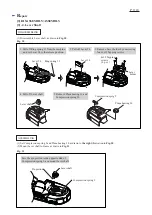
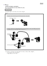
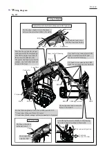
[3] DISASSEMBLY/ASSEMBLY
[3] -2. DC Motor (cont.)
DISASSEMBLING
1. Remove the following 4x18 Tapping screws.
A 6 pcs. of the screws fastening
Handle section to Frame
B 4 pcs. of the screws fastening
Motor housing to Frame
A
B
DC Motor
Gear housing
Gear housing cover


