background image


78 


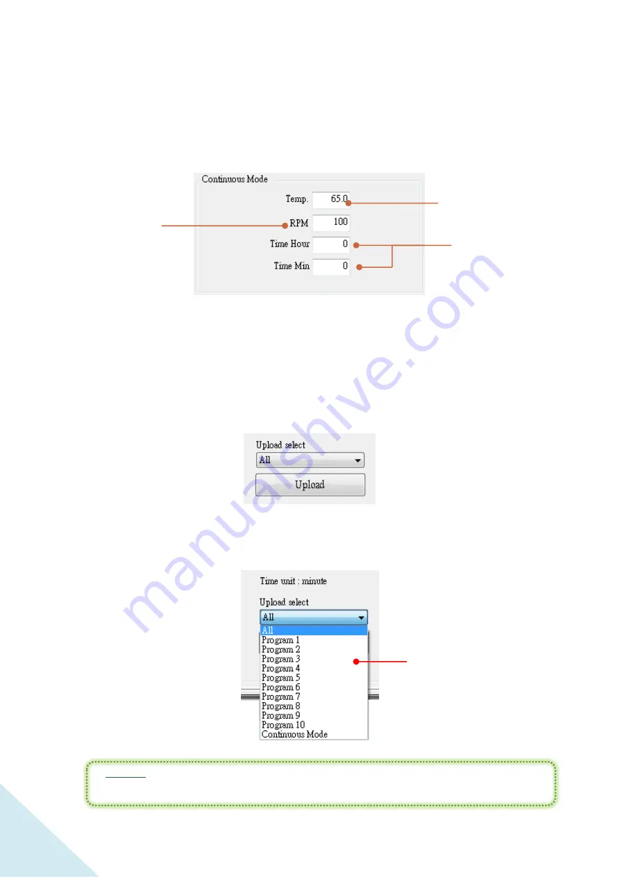
C .2-b  Continuous Mode Setting


The setting method is same as the method user use on device.   


C .2-c  Upload Button and Upload Drop-down Menu


Every time user edit or change the settings, remember to click “Upload” to send 
user’s new settings to the device. 


Or user can upload only a specific part of the settings by selecting the drop-down 
menu. 


*

Notice:


User has to click “Upload” before user try to run the operation with new 


settings. Or the device will run under the previous settings. 


The shaking speed 

during the operation. 

Range from 20 to 500. 

The incubator temperature 

during the operation. Range 

from 

15

  to 65

.


The running time of the 

operation. The maximum is 

999 hours and 59 minutes. 

Input the values of hour 

and minute in the 

respective columns. 

Drop-down Menu 

Содержание Winpact SI-200

Страница 1: ...Shaking Incubator Catalogue No SI 200 www majorsci com service majorsci com VERSION V 03B ISSUE DATE 2015 12 10 LAST REVISED DATE 2017 03 21...

Страница 2: ...2...

Страница 3: ...200 08 13 28 Adjusting the Foot Stand 34 V Operation Instruction 36 Features of Control Panel 37 Program Mode Settings 39 Naming the Program Mode Operation 40 Setting Up the Program Parameters 41 Sta...

Страница 4: ...I Troubleshooting 88 Troubleshooting Guide 88 VII Calibration Maintenance 91 Temperature Calibration 91 Maintenance 92 Allowance of Shaking Vibrating Settings 93 VIII Ordering Information 96 Warranty...

Страница 5: ...5 Packing List Winpact Shaking Incubator 1 Instruction Manual 1 Power Cord x 1 Foot Stand Pre installed x 4 Universal Platform x 1...

Страница 6: ...nt warranty 3 Use a properly grounded electrical outlet with correct voltage and current handling capacity 4 Disconnect the equipment from power supply before servicing and maintenance 5 In the event...

Страница 7: ...re that anyone involved with its operation has been instructed in both general safety practices for laboratories and safety practices for this apparatus The user is also responsible for following loca...

Страница 8: ...id opens Auto resume when the lid closes Deviations form temperature set point Over temperature warning Use high levels of precaution when using any electrical device Before connecting the electric su...

Страница 9: ...e red indicator light on the ON OFF key is on or when the device is running 3 Wait at least 5 seconds after stopping a run before handling output leads or connected apparatus 4 ALWAYS make sure that u...

Страница 10: ...ccess any HAZARDOUS LIVE parts that violate International Biosafety Regulations Symbols The symbols used on the device are explained below The symbol indicates an area where a potential shock hazard m...

Страница 11: ...for imbalance weight detects Safety interlock stops platform motion External temperature probe available upon order for precision temperature measurement Programmable or continuous mode for user appl...

Страница 12: ...rpm Communication Port RS485 External Temp Port PT 100 Heating Temperature Range Ambient 5 to 65 Output 600W Temperature Accuracy Uniformity 0 25 at 37 Timer 999 hr 59 min Continuous operation Display...

Страница 13: ...13 III Component Guide Transparent Shield Handle Control Panel Power Socket Voltage Switch 110 220V Air gas Inlet optional Power Switch Spare Installation Hole Adjustable Foot Stand RS 485...

Страница 14: ...14 PT 100 Sensor Port External Temp Port Spare Installation Hole Fan...

Страница 15: ...essories simultaneously on the platform for a more flexible setup to meet user s personal requirement Regarding the detailed instructions on the installation of incubator accessories please refer to t...

Страница 16: ...16 Loosen the flathead screws on both ends of the rack Lift up the rack from the bottom plate Flathead Screw...

Страница 17: ...ing M4 washer to fasten the bottom plate through the slots The design of slots on bottom plate allows user to arrange the tube racks in various angles without fixed angle of racks Tilting Angle Remove...

Страница 18: ...18 Place the tube rack back to the bottom plate Adjust the tilt angle of the rack before user fixes it on the bottom plate A maximum of 4 tube racks can be installed on the platform...

Страница 19: ...Phillip Screwdriver Universal Spring Rack SI 200 04 Remove four countersunk head screws at corners Put them away in the case of further usage Phillip Screwdriver User can arrange the springs in any w...

Страница 20: ...n either side on the platform instead of on any place of platform Place the spring rack on the platform and fix it onto platform with four flathead screws Leave the screws of the rest of corner untouc...

Страница 21: ...lue sticky pad 200 x 200 mm x 4 pcs M5 x 15mm Countersunk Head Screws x 4 pcs M5 15mm Flathead Screws x4 pcs Phillip Screwdriver Sticky Pad Platform Sticky Pad Remove eight countersunk head screws wit...

Страница 22: ...at the center and four flathead screws at corners Note User can arrange the four blue sticky pads in various ways for their respective usage Note The washable sticky pad can be stored by being covered...

Страница 23: ...ers of crossbars Phillip Screwdriver M5 15mm Flathead Screw Remove eight countersunk head screws with a screw driver first Universal Cushioned Crossbar Crossbar Platform SI 200 06 Remove the silicone...

Страница 24: ...he rails on both ends of crossbar platform The 2 ends contain 2 screw holes respectively The holes should face upward when user insert them into the rails Screw Hole Crossbar Rail Rail Crossbar Platfo...

Страница 25: ...he platform Flathead Screw Remember to adjust the distance of the 2 crossbars based on user s personal requirement such as the size of flasks Four countersunk head screws at the center and four flathe...

Страница 26: ...07 M4 6mm Truss Screws 4 pcs With M4Washer Phillip Screwdriver Place the microplate holder on platform and fasten the microplate holder with screws as well as M4 Washer with a screw driver onto the p...

Страница 27: ...27 A maximum of 9 microplate holders can be installed if the same type of holders is used...

Страница 28: ...of flask holder to all types of flask holder with reference of the figure below Things Required Flask Holder 50 125 250 500 1000 2000 ml in the number of user s requirement Phillip Screwdriver Phillip...

Страница 29: ...olders for one platform NOTE Try to keep the platform as balance as possible to ensure the longevity of bearings and belt NOTE Try to keep the platform as balance as possible to ensure the longevity o...

Страница 30: ...olders for one platform NOTE Try to keep the platform as balance as possible to ensure the longevity of bearings and belt NOTE Try to keep the platform as balance as possible to ensure the longevity o...

Страница 31: ...olders for one platform NOTE Try to keep the platform as balance as possible to ensure the longevity of bearings and belt NOTE Try to keep the platform as balance as possible to ensure the longevity o...

Страница 32: ...2 Flexible Arranging Possibility Example User can select and arrange the universal platform with flexibility 50 ml 500ml 125m l 1000ml 2000ml 250m l 2 5 50 0 50 0 50 0 50 0 100 100 2 5 2 5 2 5 2 5 2 5...

Страница 33: ...below Figure of the demonstration of the spring band position on flask holder for flask type above 1000 ml Spring band Figure of the demonstration of the cable tie position on flask holder for flask...

Страница 34: ...rating user can adjust the foot stands to balance the device on the floor or lab bench Four foot stands are all adjustable NOTE It is recommended to adjust the foot to keep device as balance as possib...

Страница 35: ...25 27 mm chrome wrench to loosen the foot stands Rotating the second nut either clockwise or counterclockwise with 25 27 mm chrome wrench to the favorable height Fasten the first nut counterclockwise...

Страница 36: ...ator displays 3 options Program Continuous and System Setup In this chapter we will elaborate all the functions with 5 sections features of control panel program mode settings continuous mode settings...

Страница 37: ...37 Features of Control Panel LCD Screen Key Pad 1 2 3 5 4 6 7 8...

Страница 38: ...y Press to confirm the adjusted value 6 Rpm Key Press to start shaking when under Continuous Mode 7 Start Stop Key Press to start or stop the operation 8 Temp Key Press to start heating when under Con...

Страница 39: ...39 Program Mode Settings Winpact Shaking Incubator allows user to setup the schedules based on user s requirement in Program Mode Press to enter the setting page of different programs...

Страница 40: ...elect the letter user want then press to go to the third letter And set up the rest of 5 letters in the same method as mentioned above 2 When user set up all the letters press to confirm the program n...

Страница 41: ...n and it will be highlighted Loop 3 steps in 1 loop A program can contain up to 9 loops Cycle The cycles of a loop Each loop can repeat up to 999 cycles Step Each loop contains 3 steps The operation t...

Страница 42: ...be set up to 999 times it means a loop can repeat 999 times at most To set up the parameters within each step press and the selected column will be highlighted use and to select the loop 3 Confirm the...

Страница 43: ...need all the loops in the program set the cycle at 0 in the next loop For example only 3 loops are needed in the program then just set 0 in the column of cycle in Loop4 the system will automatically...

Страница 44: ...op Cycle The remaining cycle Step The current running step Step Time The running time user set up Temp SV represents the set value of temperature PV represents the present temperature Rpm SV represent...

Страница 45: ...cubator allows user to use Continuous Mode to run the experiment under the specific circumstance User can manually control the incubator temperature shaking speed and operation time according to the e...

Страница 46: ...ation The incubator temperature ranges from 15 to 65 RPM The desired shaking speed when operation Range from 20 rpm to 500 rpm Run Time The operation time Range from 0 minute to 999 hours and 59 minut...

Страница 47: ...e 6 to check the status of all parameters like the picture below Note 6 User can change the parameters during the operation Just press and the value of shaking speed will flash Press and to move from...

Страница 48: ...ight cease immediately if user s resetting is less than the counted time Note 8 When the running time is set at 0 00 this column will count the operation time until user stops the device When the devi...

Страница 49: ...nformation Press to enter System Setup page Then use and to move from the settings and information Press to go into each setting page Notice When user adjusts the settings the selected value column wi...

Страница 50: ...or example the temperature in the flasks environment Before user changes the system setting make sure that user has installed the temperature probe correctly Select the first bar Optional device PT 10...

Страница 51: ...51 Temperature Permissible Press to enter the setting page ofTemperature Permissible This page allows user to adjust the temperature permissible range for heating detection...

Страница 52: ...he permissible value is set at 0 5 which means if user set the operation temperature at 50 the system will recognize the temperature ranging from 49 5 to 50 5 as allowable Once the temperature drops t...

Страница 53: ...e total operation time of user s shaking incubator from the first time user use The timer counts up once the operation starts either heating or shaking or both The minimum unit of the presented format...

Страница 54: ...54 System Software Version Press to go into the information page of system software version This page shows the using software version of user sWinpact Shaking Incubator Press to exit the page...

Страница 55: ...Calibration Value Press to enter the page of system calibration information The page is for maintenance and factory detection use only Users are not allowed to edit or adjust the values Press to exit...

Страница 56: ...inguish them when several devices are connected to user s personal computer Press to edit or change the machine ID and use or to adjust the numbers 9 Press to confirm the adjustment Then press to exit...

Страница 57: ...f SI 200 on user s personal computer and operate the device through the computer Installing SI 200 Software on User s Personal Computer Follow the steps below to correctly install the software on the...

Страница 58: ...gue will pop up on the screen Press Next to start installing Step4 Read the license agreement and check I Agree to accept the terms Click Next continuing the installation Or user can select Cancel to...

Страница 59: ...59 Step5 Press Browse and select the folder to install the program The default folder is set at C Program Files x86 Major Science SI 200 Or user can skip this step directly to Step6...

Страница 60: ...60 Step6 Click Next to start the installation Step7 The dialogue will show the installation status Just wait for the installation to complete...

Страница 61: ...61 Step8 When the installation complete press Close to exit the installation dialogue...

Страница 62: ...eration Notice User will need to use the USB cable to connect the device with user s computer before starting the remote control operation If the device is not connected or connected wrongly the SI 20...

Страница 63: ...e settings software information and the number of devices B Status Column Displays the connection status the selection of modes and the operation buttons C Setting Record Column Contains 3 tabs with d...

Страница 64: ...uffix when user decides to add the device number or other words into the file name Display the adjusted file name Check this box to save the operation data automatically once the device starts running...

Страница 65: ...t to see user s SI 200 software version A 4 Device Number The displayed device number is based on the setting in Machine ID on device itself Notice If 2 or more devices are set to the same device numb...

Страница 66: ...66 B Status Column B 1 B 2 B 3 B 4...

Страница 67: ...is successful Connected Disconnected B 2 Operation Mode Selection Select either Continuous Mode or Programmable Mode to run the device Notice The system will run the device based on the parameters an...

Страница 68: ...ration B 4 Exit Button Click Exit to leave the remote control program C Setting Record Column There are 3 different tabs in this column Chart C 1 Setting C 2 and History C 3 We ll elaborate the functi...

Страница 69: ...69 C 1 Chart The function of Chart tab is mainly for viewing the running data and monitoring the current status of heating and shaking speed C 1 a C 1 b C 1 c C 1 d C 1 e C 1 f C 1 g C 1 h C 1 i...

Страница 70: ...e curves of different parameters in the running chart SetValue ofTemperature PresentValue ofTemperature SetValue of Shaking Speed PresentValue of Shaking Speed SetValue of Temperature PresentValue of...

Страница 71: ...olumn all the values are unchangeable If user attempts to adjust the set values user has to stop the device and enter the setting tab to edit the parameters SetValue of Temperature PresentValue of Tem...

Страница 72: ...Notice Remember to click Apply after changing the value C 1 e Time Scale Option Column Select either Unit or All in standard option for the time scale of the chart Notice Remember to click Apply after...

Страница 73: ...anges from the minimum 10 minute to maximum 30 minutes in this moment the operation time is 56 minutes in total so the maximum can only be set at 56 at most The chart will only show the part in the se...

Страница 74: ...d user won t be able to edit the time scale The recoded data will be concentrated in 1 sheet of the chart if user applies the time scale to All in standard option And the time scale will increase alon...

Страница 75: ...ettings C 1 h Chart Printing Button Press Print Chart to print the current viewed chart C 1 i Chart Column View the current trend of user s operation in the chart column The green scale at the left si...

Страница 76: ...76 C 2 Setting Switch to Setting tab to edit or change the parameters of different modes C 2 a C 2 b C 2 c C 2 d...

Страница 77: ...nstance the time columns are both set at 0 in Loop1 Step2 and then the program will run Loop1 Step1 and skip the rest steps in Loop1 directly proceed to Loop2 Notice Remember to click Upload every tim...

Страница 78: ...pecific part of the settings by selecting the drop down menu Notice User has to click Upload before user try to run the operation with new settings Or the device will run under the previous settings T...

Страница 79: ...ress Download if user have changed or edited the settings of the 2 modes on device the system will deliver the new settings to the SI 200 software on user s computer C 3 History C 3 a C 3 b C 3 c C 3...

Страница 80: ...ve Indication Column This area helps user distinguish the curves of different parameters in the running chart SetValue ofTemperature PresentValue ofTemperature SetValue of Shaking Speed PresentValue o...

Страница 81: ...would like to review on the computer Note 13 Only log files can be viewed on the chart Notice When user has chosen the desired file click Open to load the file onto the chart C 3 c Chart Option Column...

Страница 82: ...15 If the recorded operation takes less than 20 minutes the options of All in standard and All in scale will be no use the system will locks these 2 options Notice Remember to click Apply after changi...

Страница 83: ...will influence the curve shape Image 1 Unit The time scale ranges from the minimum 0 minute to maximum 64 minutes in this case the operation time is 64 minutes in total so the maximum can only be set...

Страница 84: ...hape The time scale is set at the range from the minimum 30 minute to maximum 50 minutes in this case the operation time is 64 minutes in total so the maximum can be set at 64 at most The chart will o...

Страница 85: ...andard When All in standard is selected user won t be able to edit the range of time scale The 64 minute recoded data will be concentrated in 1 sheet of the chart if user applies the time scale to All...

Страница 86: ...scale will influence the curve shape The time scale is set at the range from the minimum 0 minute to 40 minutes in this case the operation time is 64 minutes in total so the maximum can be set at 64 a...

Страница 87: ...int the current viewed chart C 1 g Apply Button Press Apply to confirm the new settings C 1 h Chart Column View the current trend of user s operation in the chart column The green scale at the left si...

Страница 88: ...n And follow the possible causes to find the solution to user s problem If the problem remains please contact our service department for further assistance Problems Possible Causes Why I cannot start...

Страница 89: ...boot the device The platform is not working due to the motor malfunctioning Warning pops up System shut off automatically Press enter to turn off the warning Contact the service department of Major Sc...

Страница 90: ...losed Close the shield to start up the operation again The device is under dangerous condition due to over shaking Icon turns red System slows down the shaking speed automatically to the range which i...

Страница 91: ...perature sensor on their own Follow the instruction below to finish the temperature calibration Step 1 Turn the incubator off first Press and hold then turn on the power at the same time User can see...

Страница 92: ...ure probe Use and to increase or decrease the value Step 5 Press to store the value of offset temperature The adjustment user entered will be applied onto measured temperature at any time point system...

Страница 93: ...g environment for the device It is highly recommended that user conduct step 1 before step 2 for balance calibration after the first installation of device Step1 Hold the enter key until the number co...

Страница 94: ...for Axis X Y Z PD 10 for Axis X Y Z frequency Thus if user would like to level up the sensitivity it is suggested to set the value of Axis X Y Z PD below 4 the range of Axis X Y X PD is 0 6 Axis X Y...

Страница 95: ...Z PD is corresponding with the values of axis X Y Z frequency respectively Use and to switch to the parameters and press to enter the corresponding values Use and to increase or decrease the value Pr...

Страница 96: ...200 03 Adjustable Angle Tube Rack 16 50ml SI 200 04 Universal Spring Rack SI 200 05 Sticky Pad Platform SI 200 06 Universal Cushioned Crossbar SI 200 07 Microplate Holder SI 200 08 Flask Holder 50ml S...

Страница 97: ...limited to the receipt of reasonable proof by the customer that the defect is embraced within the terms of the warranty All claims made under this warranty must be presented to Major Science within o...

Отзывы: