©
2020 Sensata Technologies
Page 41
Operation
3.6 Inverter
Startup
ON/OFF Switch
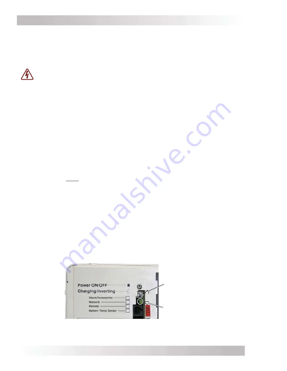
– The inverter can be turned on and off by lightly pressing and releasing the
Power ON/OFF switch on the front of the inverter (refer to Figure 3-11). When the inverter is
fi
rst
connected to the batteries, or when its automatic protection circuit has turned the inverter off, the
ON/OFF switch will need to be pressed to start the unit (or reset per Section 4.4). Once the inverter
has been turned on, pressing the Power ON/OFF switch alternately turns the inverter on and off.
WARNING:
The Power ON/OFF switch does not turn on or off the charger feature,
or remove pass-thru power. If AC power (shorepower or generator) is connected and
quali
fi
ed on the AC input, this AC power will also be available on the AC output and is
not controlled by the Power ON/OFF switch.
Inverter Status LED Indicator
– The status indicator for the inverter is a green LED (Light
Emitting Diode) that provides information on the operational mode of the inverter. Watch this
indicator (refer to Figure 3-11) for at least 10 seconds to determine the inverter’s operational
condition from the information below:
• Off
– Indicates the inverter is off—there is no AC power (inverter, shorepower, or generator)
at the inverter’s output terminals. If the LED stays off after pressing the ON/OFF switch,
there is a fault condition such as: low battery, high battery, overload, over-temperature, or
an internal fault. Refer to the Troubleshooting section to help diagnose the fault condition.
• Slow
Flash
(blinks on for 4 seconds, then off for 4 seconds) – Indicates the batteries are
fl
oat charging and the inverter is in Standby mode (any external AC power that is connected
to the inverter’s input is passing through the inverter and powering the inverter’s AC loads).
• Medium
Flash
(blinks on once every two seconds) – Indicates the inverter is Inverting,
using energy from the battery and providing full power to connected loads.
• Fast
Flash
(blinks on once every second) –
When AC power is not connected to the inverter’s input:
Indicates the inverter is Searching—
conserving power and waiting for a load to be turned on that meets or exceeds the
Search
Watts
parameter (5 Watts = default setting).
When AC power is connected to the inverter’s input:
Indicates absorb charging, and the
inverter is in Standby mode (external AC power connected to the inverter’s input is passing
through the inverter and is powering the AC loads connected to the inverter’s output).
• Very
Fast
Flash
(blinks on/off very quickly—
fl
utters) – Indicates the inverter is in EQ charge
mode (requires remote to enable), or the inverter is continuously in reset. If a remote was
not used to enable the equalize charge, then the inverter is likely in reset. Refer to the
Troubleshooting section to help diagnose/clear the fault condition.
• On
(solid) – Indicates bulk charging, and the inverter is in Standby mode (the external
AC power that is connected to the inverter’s input is passing through the inverter and is
powering the AC loads connected to the inverter’s output).
Charging/Inverting
Status LED indicator
Power ON/OFF
pushbutton switch
Figure 3-11, Power Switch and Status Indicator


