Magnetrol Jupiter JM4 Скачать руководство пользователя страница 29

ORI-XXX Jupiter Magnetostrictive Transmitters 

57

56 

ORI-46.650 Jupiter Magnetostrictive Transmitters

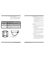
2.5.5  Power Supply Requirements   

2.5.5.1  Safe Operating Area

2.5.5.2  Terminal Voltage

Operational Mode

Current Consumption

Vmin

Vmax

HART

General Purpose

4mA

20mA

16.25V

11V

36V

36V

Intrinsically Safe

4mA

20mA

16.25V

11V

28.6V

28.6V

Explosion Proof

4mA

20mA

16.25V

11V

36V

36V

Fixed Current-Solar Power Operation (PV transmitter via HART)

General Purpose

10mA

1

11V

36V

Intrinsically Safe

10mA

1

11V

28.6V

HART Multi-Drop Mode (Fixed Current)

Standard

4mA

1

16.25V

36V

Intrinsically Safe1

4mA

1

16.25V

28.6V

FOUNDATION fieldbus 

Supply/Terminal Voltage

9V to 17.5V

9V to 17.5V

9V to 17.5V

1

 Start-up current 12mA minimum.
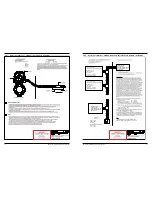
0

Vsupply (Loop Supply Voltage)

Typical HART

4-20 mA

Operating Area

Digital Solar Mode

Safe Operating Area

16.25 V

591 

Ω

1136 

Ω

360 

Ω

24 V

18.9 V

36 V

Loop

R

J       M       4

5

1 2 3

 |  BASIC MODEL NUMBER

JM4

Jupiter 4th Generation Magnetostrictive Level Transmitter

4

 | POWER

5

24 VDC Two Wire

5

 | SIGNAL OUTPUT

1

4-20 mA with HART

2

Foundation Fieldbus Communications

6

 | SAFETY OPTIONS

1

SIL 2 Suitable - 3rd party FMEDA

7

 | ACCESSORIES/MOUNTING

1, 2, B, & C Not Available When 8th Digit = 3, B, and D.

0

No Digital Display and Keypad - Integral

1

No Digital Display and Keypad - Remote 36” (0.91m)

2

No Digital Display and Keypad - Remote 144” (3.6m)

A

Digital Display and Keypad - Integral

B

Digital Display and Keypad - Remote 36” (0.91m)

C

Digital Display and Keypad - Remote 144” (3.6m)

| AREA CLASSIFICATION

3, B, & D Not Available When 7th Digit = 1, 2, B, & C.

When Digit 5 = 1

1

Intrinsically Safe (FM & FM

C

)

3

Explosion-Proof (FM & FM

C

)

0

General Purpose, Weatherproof (IP 67)

A

Intrinsically Safe (ATEX & IEC)

C

Non-Incendive (FM & FM

C

)/Non-Sparking (ATEX & IEC)

D

Dust Ignition Proof (FM, FMc, ATEX, IECEx)

When Digit 5 = 2

1

FISCO FIELD DEVICE (FM & CSA)

9

 | HOUSING

1

Aluminum, Dual-Component

2

316 SS, Dual-Component

10

 | CONDUIT CONNECTION

0

1/2” NPT

1

M20

2

1/2” NPT with Sunshade

3

M20 with Sunshade

1

3

2

4

5

6

7

8

9

10

2.6   Model Number

Transmitter

Содержание Jupiter JM4

Страница 1: ...Model JM4 Magnetostrictive Level Transmitter HART Installation and Operating Manual Software v1 x...

Страница 2: ...ation labor claims direct or consequential damage or expense arising from the installation or use of equipment There are no other warranties expressed or implied except special written warranties cove...

Страница 3: ...nents or connector pins Make sure that all electrical connections are completely made and none are partial or floating Ground all equipment to a reli able earth ground 1 1 4 Site Preparation Power Sup...

Страница 4: ...eft to right in Figure 1 4 top mount top mount offset bottom mount offset All of these configurations are available with one or two magnetic floats two floats are necessary to measure total AND interf...

Страница 5: ...th an insulation blanket secure the blanket over the chamber then be sure to place the transmitter in the smaller of the two grooves leaving the larger groove for visual indication Figure 1 6b 1 2 7 V...

Страница 6: ...e to the terminal 6 Replace and tighten the cover to the transmitter wiring compartment before applying power 1 4 2 Intrinsically Safe An Intrinsically Safe IS installation potentially has flammable m...

Страница 7: ...avigation and data entry The Model JM4 user interface is hierarchical in nature best de scribed as a tree structure Each level in the tree contains one or more items Items are either menu labels or pa...

Страница 8: ...The user password can be changed to any numerical value up to 59999 When the transmitter is programmed for password protection a password is required whenever configuration values are changed User Pa...

Страница 9: ...AIN MENU will result in an LCD presentation as shown at left The small down arrow shown at the right hand side of the screen is the indication that more items are available below and can be accessed b...

Страница 10: ...rs Upper Thickness Units Inches Feet Millimeters Centimeters Meters Device Setup Main Menu Home Screen Product Name read only Orion S N read only DIGITAL BOARD read only ANALOG BOARD read only Physica...

Страница 11: ...l Display Config Advanced Config Factory Config Blocking Distance 0 to 50 feet 0 m to 15 m Minimum Separation 0 to 28 inches 0 cm to 71 cm Zero Offset 50 to 50 feet 15 m to 15 m Level Trim 2 to 2 feet...

Страница 12: ...JM4 software Device Descriptions Refer to your HART Communicator Manual for update instructions 1 6 1 Connections A HART communicator can be operated from a remote loca tion by connecting it to a rem...

Страница 13: ...6 4 HART Menu Model JM4 NOTE Numbered menu boxes below correspond to numbered tables on Section 1 6 5 1 PV 2 PV Analog Output 3 PV Output 4 Device Setup 5 Setup Wizard 6 Diagnostics 7 Measured Values...

Страница 14: ...his value corresponds to the level of the upper surface 2 PV Analog Output Digital representation that tracks the Analog Output Number 1 under normal operating modes Analog Output Value Value that tra...

Страница 15: ...ion or calibration has been changed by a host application or from a local operator interface 9 Device ID Uniquely identifies the Field Device when combined with the Manufacturer Identification and Dev...

Страница 16: ...n operational endpoint from which the alarms associated with the Analog Value and the alarms associated with the Digital Value representation are derived Ifc 4mA Set Point Thk 4mA Set Point Vol 4mA Se...

Страница 17: ...t to match the polarity of the first portion of the sine wave signal of a direct insertion float or the first portion of the M shaped signal of an external mount probe Ifc Lvl Polarity 1 6 5 HART Menu...

Страница 18: ...es only 1 6 5 HART Menu Items cont 19 Display Description 1 Present Temperature Present temperature measured in the electronics compartment 2 Max Temperature Maximum temperature measured in the electr...

Страница 19: ...e mode this value corresponds to the strength of the upper level signal 6 Ifc Echo Strength Relative strength of the interface level signal 7 Analog Output Allows for configuration of the 4 20mA Analo...

Страница 20: ...valuable proactive method of troubleshooting The device not only tells the user what wrong but also and more impor tantly offers suggestions on how to solve the problem All of this information can be...

Страница 21: ...Specification and Maintenance Required The FOUNDATION fieldbus transmitter version of the Model JM4 was implemented according to the Field Diagnostics Pro file which is consistent with the objectives...

Страница 22: ...upper level threshold Check echo curve for noise levels Echo Rejection may be required Consult Factory Swipe probe with pocket magnet to eliminate possibility of residual magnetism High Noise Ifc Thre...

Страница 23: ...rtical Flat factory default Vessel Type Vertical Elliptical Vertical Spherical Vertical Conical Custom Table Rectangular Horizontal Flat Horizontal Elliptical Horizontal Spherical or Spherical Note Ve...

Страница 24: ...roubleshooting this parameter gives the user the ability to reset the Model JM4 transmitter configuration Unique to the Model JM4 transmitter is the ability for Orion In struments to fully pre configu...

Страница 25: ...EC60079 11 2011 IEC60079 15 2010 IEC60079 31 2008 SPECIAL CONDITIONS OF USE 1 The enclosure contains aluminum and is considered to present a potential risk of ignition by impact or friction Care must...

Страница 26: ...NSTALLATION REFERENCE ALL APPLICABLE NOTES FROM PAGE 2 99 5074 001 Ui Vmax 24V Ii Imax 280mA Pi 1 93W or Any approved termination on with R 90 100 C 0 2 2 F Any FM CSA Approved Intrinsically Safe Asso...

Страница 27: ...upon request Environment Ambient Temperature Range Transmitter 40 F to 176 F 40 C to 80 C LCD 5 F to 176 F 20 C to 80 C Process Temperature External Mount 320 F to 850 F 195 C to 454 C Direct Inserti...

Страница 28: ...tion 75 NPT High Temp Cryo Direct Insertion 1 BSP 16 92 429 7 Direct Insertion 2 BSP 17 17 436 Direct Insertion 2 NPT 2 5 4 Physical Specifications Transmitter inches mm 18 92 480 5 22 92 582 1 Direct...

Страница 29: ...SIC MODEL NUMBER JM4 Jupiter 4th Generation Magnetostrictive Level Transmitter 4 POWER 5 24 VDC Two Wire 5 SIGNAL OUTPUT 1 4 20 mA with HART 2 Foundation Fieldbus Communications 6 SAFETY OPTIONS 1 SIL...

Страница 30: ...ct Insertion float provided or unit is External Mount Jupiter 99 Custom Direct Insertion float not listed in standard offering below One Float Total Level Only Digit 10 1 AA 316L SS MIN SG 0 83 2 00 O...

Страница 31: ...r External Mount Probe 0 0 0 2 1 3 2 4 5 6 7 8 9 10 11 12 13 14 15 8 INSTALLATION CONSIDERATIONS 0 No mounting clamps required Chamber Clamp Sizes for MLI Mount Without High Temperature Insulation 1 2...

Страница 32: ...closure Fault A defect or failure in a circuit The current mA value unit defaults to 3 6 22 or Hold when a diagnostic condition occurs Feedthrough A small connecting cavity between the main housing co...

Страница 33: ...to user s meter DCS input etc Two Wire An electrical instrument design that uses one set of wires to provide both the supply power and process measurement signal The process measurement is achieved b...

Страница 34: ...probe 4mA or 0 20mA or 100 Is moderate to heavy vibration present Is turbulence or flow present Additional application details that could impact performance Will existing chamber or stilling well be u...

Страница 35: ...red trademarks of Magnetrol International Incorporated HART is a registered trademark of the HART Communication Foundation PACTware is trademark of PACTware Consortium CSA logotype is a registered tra...

Отзывы: